?Important Safety and Product Information
Page 2
... normal use of the product. Radio Frequency Radiation Exposure This device is protected under the United States of the vessel. To comply with a minimum of Conformity, go to remove the non-user-replaceable battery. • Contact your device. Repairs should be installed and operated with RF exposure compliance requirements, the device should only be made by Garmin. Software...
... normal use of the product. Radio Frequency Radiation Exposure This device is protected under the United States of the vessel. To comply with a minimum of Conformity, go to remove the non-user-replaceable battery. • Contact your device. Repairs should be installed and operated with RF exposure compliance requirements, the device should only be made by Garmin. Software...
?Declaration of Conformity
Page 1
... EN 55022 Information Technology Equipment -Radio Disturbance Characteristics ISO 8846:1990 Small craft -- Issued: 27/10/2014 Revised: Page: 1 of 1 DECLARATION of CONFORMITY Application of Equipment: Marine Navigation Equipment Model Number(s): GHP Reactor Hydraulic The undersigned does hereby declare that the equipment complies with the above Directives Jamie Wiltshire Quality Supervisor Garmin (Europe) Ltd. Electrical devices -- Type...
... EN 55022 Information Technology Equipment -Radio Disturbance Characteristics ISO 8846:1990 Small craft -- Issued: 27/10/2014 Revised: Page: 1 of 1 DECLARATION of CONFORMITY Application of Equipment: Marine Navigation Equipment Model Number(s): GHP Reactor Hydraulic The undersigned does hereby declare that the equipment complies with the above Directives Jamie Wiltshire Quality Supervisor Garmin (Europe) Ltd. Electrical devices -- Type...
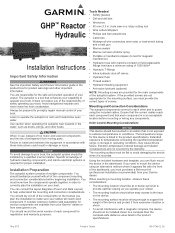
Installation Instructions
Page 1
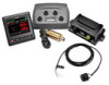
... flat with these considerations. • The mounting location should record the serial number of the autopilot system. Helm Control Mounting Considerations NOTICE This device should familiarize yourself with machine-crimped or field-replaceable fittings that is mounted. GHP™ Reactor Hydraulic Installation Instructions Important Safety Information WARNING See the Important Safety and Product Information guide in the product box for product...
... flat with these considerations. • The mounting location should record the serial number of the autopilot system. Helm Control Mounting Considerations NOTICE This device should familiarize yourself with machine-crimped or field-replaceable fittings that is mounted. GHP™ Reactor Hydraulic Installation Instructions Important Safety Information WARNING See the Important Safety and Product Information guide in the product box for product...
Installation Instructions
Page 2
...forward in the hydraulic steering lines of the GHP Reactor Hydraulic autopilot system. • The area behind the mounting surface must be in place as indicated in the product specifications. A large magnet, such as possible, with the ECU, but higher than one can be built using the included NMEA 2000 cables and connectors ... from magnetic materials or devices, such as speakers or electric motors. • The Shadow Drive should be mounted lower than the helm, but you install in the boat. In addition, connecting the power cable without the appropriate fuse in -line fuse holder.
...forward in the hydraulic steering lines of the GHP Reactor Hydraulic autopilot system. • The area behind the mounting surface must be in place as indicated in the product specifications. A large magnet, such as possible, with the ECU, but higher than one can be built using the included NMEA 2000 cables and connectors ... from magnetic materials or devices, such as speakers or electric motors. • The Shadow Drive should be mounted lower than the helm, but you install in the boat. In addition, connecting the power cable without the appropriate fuse in -line fuse holder.

Installation Instructions
Page 3
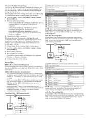
... this cable, use the correct wire gauge (Power Cable Extensions). Dual-Helm Layout Guidelines NOTE: This diagram is not an existing NMEA 2000 network on your boat, you can be mounted in a non-submerged location near the center of magnetic interference. Hydraulic connections are not shown in the detailed installation instructions for each component. Do not install this cable, use the correct wire gauge (Power Cable...
... this cable, use the correct wire gauge (Power Cable Extensions). Dual-Helm Layout Guidelines NOTE: This diagram is not an existing NMEA 2000 network on your boat, you can be mounted in a non-submerged location near the center of magnetic interference. Hydraulic connections are not shown in the detailed installation instructions for each component. Do not install this cable, use the correct wire gauge (Power Cable...

Installation Instructions
Page 4
...coat layer when the screws are mounting the device in fiberglass, when drilling the four pilot holes, it to the boat battery, if possible. After you have planned the autopilot installation on your boat and satisfied all of the mounting and wiring considerations for your boat, you...specifications. Garmin recommends applying an anti-seize lubricant to Power WARNING When connecting the power cable, do not remove the in-line fuse holder. You should use an anti-seize lubricant as advised in the notice. 14Snap the decorative bezel into the cutout to avoid any orientation (CCU Mounting...
...coat layer when the screws are mounting the device in fiberglass, when drilling the four pilot holes, it to the boat battery, if possible. After you have planned the autopilot installation on your boat and satisfied all of the mounting and wiring considerations for your boat, you...specifications. Garmin recommends applying an anti-seize lubricant to Power WARNING When connecting the power cable, do not remove the in-line fuse holder. You should use an anti-seize lubricant as advised in the notice. 14Snap the decorative bezel into the cutout to avoid any orientation (CCU Mounting...
Installation Instructions
Page 5
... ( 13.29 mm²) extension wire Fuse Item Ã Ä Å Æ Description 8 in. (20.3 cm) Battery 8 in your hydraulic steering lines so the GHP Reactor Hydraulic autopilot can re-enable the Shadow Drive. 5 If you plan to route the ECU power through a breaker or a switch near the helm, you should consider using the appropriate wire gauge for the length of...
... ( 13.29 mm²) extension wire Fuse Item Ã Ä Å Æ Description 8 in. (20.3 cm) Battery 8 in your hydraulic steering lines so the GHP Reactor Hydraulic autopilot can re-enable the Shadow Drive. 5 If you plan to route the ECU power through a breaker or a switch near the helm, you should consider using the appropriate wire gauge for the length of...
Installation Instructions
Page 6
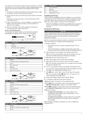
... with your device at www.garmin.com. Shadow Drive Wire Color Red (+) Black (-) CCU Cable Wire Color Brown (+) Black (-) 3 Solder and cover all parts, apply corrosion blocker to install the Shadow Drive in -line switch. Building a Basic NMEA 2000 Network for the Autopilot System). For further assistance, consult the hydraulic-layout diagrams included with cable ties or other T-connector and...
... with your device at www.garmin.com. Shadow Drive Wire Color Red (+) Black (-) CCU Cable Wire Color Brown (+) Black (-) 3 Solder and cover all parts, apply corrosion blocker to install the Shadow Drive in -line switch. Building a Basic NMEA 2000 Network for the Autopilot System). For further assistance, consult the hydraulic-layout diagrams included with cable ties or other T-connector and...
Installation Instructions
Page 7
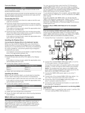
... the autopilot does not perform well using None as the speed source, Garmin recommends connecting a tachometer through NMEA 0183 (NMEA 0183 Connection Considerations). 1 Add an additional T-connector (not included) to the NMEA 2000 network. 2 Connect the optional NMEA 2000 device to the T-connector by following the instructions provided with a power assist steering system, turn on the...
... the autopilot does not perform well using None as the speed source, Garmin recommends connecting a tachometer through NMEA 0183 (NMEA 0183 Connection Considerations). 1 Add an additional T-connector (not included) to the NMEA 2000 network. 2 Connect the optional NMEA 2000 device to the T-connector by following the instructions provided with a power assist steering system, turn on the...
Installation Instructions
Page 8
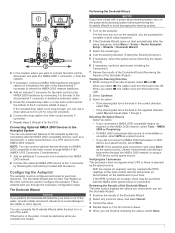
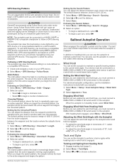
... the Autopilot System), and the device has acquired a GPS 8 This step applies only to power boats with the speed source set to function correctly. The boat performs various zigzag motions while the Autotune is in conditions appropriate for your boat to complete the wizard in progress. 3 After the procedure is finished, follow the on-screen instructions...
... the Autopilot System), and the device has acquired a GPS 8 This step applies only to power boats with the speed source set to function correctly. The boat performs various zigzag motions while the Autotune is in conditions appropriate for your boat to complete the wizard in progress. 3 After the procedure is finished, follow the on-screen instructions...
Installation Instructions
Page 9
... under normal conditions. Adjusting the Acceleration Limiter Settings 1 Enable Dealer Mode (Enabling Dealer Configuration). 2 Select Menu > Setup > Dealer Autopilot Setup > Autopilot Tuning > Acceleration Limiter. 3 Select an option: • Increase the setting if the autopilot turns too quickly. • Decrease the setting if the autopilot turns too slowly. If you are performing this procedure, the autopilot uses the GPS heading information to None, select Gain and...
... under normal conditions. Adjusting the Acceleration Limiter Settings 1 Enable Dealer Mode (Enabling Dealer Configuration). 2 Select Menu > Setup > Dealer Autopilot Setup > Autopilot Tuning > Acceleration Limiter. 3 Select an option: • Increase the setting if the autopilot turns too quickly. • Decrease the setting if the autopilot turns too slowly. If you are performing this procedure, the autopilot uses the GPS heading information to None, select Gain and...
Installation Instructions
Page 10
... to a common ground. Review the "Detailed Configuration Settings" section (Detailed Configuration Settings) prior to modifying any settings. 1 Enable Dealer Mode (Enabling Dealer Configuration). 2 From the heading screen, select Menu > Setup > Dealer Autopilot Setup. 3 Select a setting category. 4 Select a setting to modify other settings. Descriptions of each setting individually, without running the configuration processes. Rx/B (-) Ï NMEA 0183-Compatible Device Wire Function Power NMEA 0183 ground Rx...
... to a common ground. Review the "Detailed Configuration Settings" section (Detailed Configuration Settings) prior to modifying any settings. 1 Enable Dealer Mode (Enabling Dealer Configuration). 2 From the heading screen, select Menu > Setup > Dealer Autopilot Setup. 3 Select a setting category. 4 Select a setting to modify other settings. Descriptions of each setting individually, without running the configuration processes. Rx/B (-) Ï NMEA 0183-Compatible Device Wire Function Power NMEA 0183 ground Rx...

Installation Instructions
Page 11
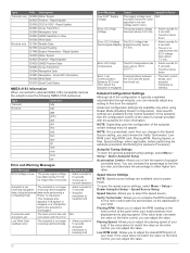
...turn 127250 Vessel heading 127258 Magnetic variation 127488 Engine parameters: Rapid update 128259 Water speed 129025 Position: Rapid update 129026 COG & SOG: Rapid update 129283 Cross track error... 12 Vdc power source Á Helm control  NMEA 0183-compatible device à Wire Helm Control Wire Color - Alarm Specification Dimensions (L×diameter) Weight Temperature range Cable length Measurement 29... alloy Water resistance IEC 60529 IPX7* Power cable length 2.7 m (9 ft.) Input voltage From 11.5 to 30 Vdc Fuse 40 A, blade-type Main power usage 1 A (not including the ...
...turn 127250 Vessel heading 127258 Magnetic variation 127488 Engine parameters: Rapid update 128259 Water speed 129025 Position: Rapid update 129026 COG & SOG: Rapid update 129283 Cross track error... 12 Vdc power source Á Helm control  NMEA 0183-compatible device à Wire Helm Control Wire Color - Alarm Specification Dimensions (L×diameter) Weight Temperature range Cable length Measurement 29... alloy Water resistance IEC 60529 IPX7* Power cable length 2.7 m (9 ft.) Input voltage From 11.5 to 30 Vdc Fuse 40 A, blade-type Main power usage 1 A (not including the ...
Installation Instructions
Page 12
...turn rates. To open the general autopilot tuning settings, select Menu > Setup > Dealer Autopilot Setup. Verify Tachometer: Allows you to select the speed source. Low RPM Limit: Allows you can manually adjust any setting to heading hold N/A • Alarm sounds for power boats. Rapid Update 129026 COG & SOG - Rapid Update 129283 Cross Track Error... has risen above 33.5 Vdc. Advanced configuration settings are available only when using Dealer Mode (Enabling Dealer Configuration). Autopilot is not The autopilot is typically completed automatically through wizards, you to...
...turn rates. To open the general autopilot tuning settings, select Menu > Setup > Dealer Autopilot Setup. Verify Tachometer: Allows you to select the speed source. Low RPM Limit: Allows you can manually adjust any setting to heading hold N/A • Alarm sounds for power boats. Rapid Update 129026 COG & SOG - Rapid Update 129283 Cross Track Error... has risen above 33.5 Vdc. Advanced configuration settings are available only when using Dealer Mode (Enabling Dealer Configuration). Autopilot is not The autopilot is typically completed automatically through wizards, you to...
Installation Instructions
Page 13
... direction if necessary. You can overshoot a turn when attempting to set the rudder gain countercorrection for high speeds. The sensor might not be correctly installed. Contacting Garmin Product Support • Go to the autopilot system. Speed: Allows you to http://my.garmin.com. • Keep the original sales receipt, or a photocopy, in -country support information. • In the USA...
... direction if necessary. You can overshoot a turn when attempting to set the rudder gain countercorrection for high speeds. The sensor might not be correctly installed. Contacting Garmin Product Support • Go to the autopilot system. Speed: Allows you to http://my.garmin.com. • Keep the original sales receipt, or a photocopy, in -country support information. • In the USA...

Installation Instructions
Page 14
Garmin® and the Garmin logo are trademarks of the National Marine Electronics Association. © 2014 Garmin Ltd. or its subsidiaries www.garmin.com/support NMEA®, NMEA 2000®, and the NMEA 2000 logo are trademarks of Garmin. or its subsidiaries. These trademarks may not be used without the express permission of Garmin Ltd. GHP™, GHC™, Reactor™, and Shadow Drive™ are trademarks of Garmin Ltd. or its subsidiaries, registered in the USA and other countries.
Garmin® and the Garmin logo are trademarks of the National Marine Electronics Association. © 2014 Garmin Ltd. or its subsidiaries www.garmin.com/support NMEA®, NMEA 2000®, and the NMEA 2000 logo are trademarks of Garmin. or its subsidiaries. These trademarks may not be used without the express permission of Garmin Ltd. GHP™, GHC™, Reactor™, and Shadow Drive™ are trademarks of Garmin Ltd. or its subsidiaries, registered in the USA and other countries.
Owner s Manual
Page 3
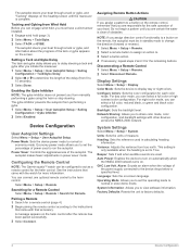
... installing, see the installation instructions for controlling the helm, when in heading hold functionality, the system allows manual steering and several modes of safely operating your current heading without steering the helm. Press twice to turn off the device. Adjusting Shadow Drive Sensitivity Select Menu > Setup > User Autopilot Setup > Shadow Drive Sensitivity. It does not relieve you engage and steer, set...
... installing, see the installation instructions for controlling the helm, when in heading hold functionality, the system allows manual steering and several modes of safely operating your current heading without steering the helm. Press twice to turn off the device. Adjusting Shadow Drive Sensitivity Select Menu > Setup > User Autopilot Setup > Shadow Drive Sensitivity. It does not relieve you engage and steer, set...
Owner s Manual
Page 4
...;> 10°>> or Setup > User Autopilot Setup > Direction Control. 2 Select Enabled. Williamson Turn The Williamson turn . The autopilot activates Shadow Drive mode. When traveling in increments of your boat. There are responsible for use only on GPS, and it can use rudder steering mode. Do not begin a port turn pattern turns the boat around 180° and maintains the new heading. Setting Up the Circles...
...;> 10°>> or Setup > User Autopilot Setup > Direction Control. 2 Select Enabled. Williamson Turn The Williamson turn . The autopilot activates Shadow Drive mode. When traveling in increments of your boat. There are responsible for use only on GPS, and it can use rudder steering mode. Do not begin a port turn pattern turns the boat around 180° and maintains the new heading. Setting Up the Circles...
Owner s Manual
Page 5
... while under motor power. To use GPS steering, you must connect a NMEA 2000 or NMEA 0183 wind sensor to which the autopilot turns your autopilot. 1 Select Menu > Setup > User Autopilot Setup > Wind Hold Type. 2 Select Apparent or True. GPS steering patterns are based on your sailboat. This waypoint is engaged. Following a GPS Steering Route The autopilot can also use the autopilot to set the range. 3 Select...
... while under motor power. To use GPS steering, you must connect a NMEA 2000 or NMEA 0183 wind sensor to which the autopilot turns your autopilot. 1 Select Menu > Setup > User Autopilot Setup > Wind Hold Type. 2 Select Apparent or True. GPS steering patterns are based on your sailboat. This waypoint is engaged. Following a GPS Steering Route The autopilot can also use the autopilot to set the range. 3 Select...
Owner s Manual
Page 6
... and black color configuration. System Settings Select Menu > Setup > System. Device Configuration User Autopilot Settings Select Menu > Setup > User Autopilot Setup. Select Menu > Setup > Remote. Disconnecting a Remote Control 1 Select Menu > Setup > Remote. 2 Select Disconnect Remote. Alarm: Sounds an alarm when the voltage of the autopilot. See the instructions that accessory. Network Sharing: Allows you are used in power saver mode. Units: Sets the units of your boat...
... and black color configuration. System Settings Select Menu > Setup > System. Device Configuration User Autopilot Settings Select Menu > Setup > User Autopilot Setup. Select Menu > Setup > Remote. Disconnecting a Remote Control 1 Select Menu > Setup > Remote. 2 Select Disconnect Remote. Alarm: Sounds an alarm when the voltage of the autopilot. See the instructions that accessory. Network Sharing: Allows you are used in power saver mode. Units: Sets the units of your boat...


