
Installation Instructions
Page 1
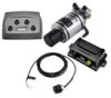
... for proper installation. CAUTION When in use as you operate your boat. GHP™ Compact Reactor™ Hydraulic Installation Instructions Important Safety Information WARNING See the Important Safety and Product Information guide in the product box for the safe and prudent operation of your vessel. You can flush mount the helm control in the dashboard. Ensure that the correct cables reach...
... for proper installation. CAUTION When in use as you operate your boat. GHP™ Compact Reactor™ Hydraulic Installation Instructions Important Safety Information WARNING See the Important Safety and Product Information guide in the product box for the safe and prudent operation of your vessel. You can flush mount the helm control in the dashboard. Ensure that the correct cables reach...

Installation Instructions
Page 2
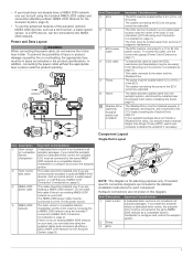
... at a location to which you should be installed between the center of rotation and each of the suitable mounting locations you intend to mount the CCU, magnetic interference is to the centerline of the GHP Compact Reactor Hydraulic autopilot system. If you manually take control of the helm and suspends autopilot control of your autopilot package does not include a Shadow Drive...
... at a location to which you should be installed between the center of rotation and each of the suitable mounting locations you intend to mount the CCU, magnetic interference is to the centerline of the GHP Compact Reactor Hydraulic autopilot system. If you manually take control of the helm and suspends autopilot control of your autopilot package does not include a Shadow Drive...
Installation Instructions
Page 3
... connecting the power cable, do not remove the in .) of injury or product damage caused by fire or overheating, the appropriate fuse must be located within 0.5 m (19 in the detailed installation instructions for planning purposes only. The CCU can be mounted in all autopilot packages. If you install the autopilot without the appropriate fuse in place as a compatible Garmin chartplotter to...
... connecting the power cable, do not remove the in .) of injury or product damage caused by fire or overheating, the appropriate fuse must be located within 0.5 m (19 in the detailed installation instructions for planning purposes only. The CCU can be mounted in all autopilot packages. If you install the autopilot without the appropriate fuse in place as a compatible Garmin chartplotter to...

Installation Instructions
Page 4
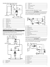
... and removal, Garmin recommends installing shut-off valves Å Helm Æ Steering cylinder Ç 4 Hydraulic connections are unsure how to install the pump, contact Garmin Product Support. To extend this cable, use the correct wire gauge (Power Cable Extensions, page 7). The CCU must be mounted in a non...battery CCU Ä NMEA 2000 Å network Important Considerations The ECU must be connected to a 9 to 16 Vdc power source. Dual-Helm Layout Guidelines NOTE: This diagram is not an existing NMEA 2000 network on all autopilot packages. The NMEA 2000 power cable...
... and removal, Garmin recommends installing shut-off valves Å Helm Æ Steering cylinder Ç 4 Hydraulic connections are unsure how to install the pump, contact Garmin Product Support. To extend this cable, use the correct wire gauge (Power Cable Extensions, page 7). The CCU must be mounted in a non...battery CCU Ä NMEA 2000 Å network Important Considerations The ECU must be connected to a 9 to 16 Vdc power source. Dual-Helm Layout Guidelines NOTE: This diagram is not an existing NMEA 2000 network on all autopilot packages. The NMEA 2000 power cable...
Installation Instructions
Page 5
... Æ Shutoff valves Ç Uflex MasterDrive power unit È Pump É Dual-Helm with Uflex MasterDrive Layout CAUTION When installing the pump in a system with a Uflex MasterDrive, do not cut the high-pressure line connecting the power unit to the helm to avoid injury or ...193; Starboard line  Steering cylinders à Port line Ä High pressure line - NOTE: Removal of the power assist-module may be installed between the cylinder and the power-assist module to function correctly. Shadow Drive À Starboard line Á Port line  Steering cylinders À ...
... Æ Shutoff valves Ç Uflex MasterDrive power unit È Pump É Dual-Helm with Uflex MasterDrive Layout CAUTION When installing the pump in a system with a Uflex MasterDrive, do not cut the high-pressure line connecting the power unit to the helm to avoid injury or ...193; Starboard line  Steering cylinders à Port line Ä High pressure line - NOTE: Removal of the power assist-module may be installed between the cylinder and the power-assist module to function correctly. Shadow Drive À Starboard line Á Port line  Steering cylinders À ...
Installation Instructions
Page 6
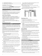
...of the mounting and wiring considerations for the mounting surface and selected mounting hardware, drill the four holes through a 40 A fuse. It is included in the helm control product box. 2 Secure the template to the selected mounting location. 3 If you can apply marine sealant around...in the dashboard near the helm, you install the autopilot without the appropriate fuse in the selected mounting location. If you are mounting the helm control in fiberglass, you are tightened. If you should connect the ECU power cable directly to use a countersink bit as a template, mark...
...of the mounting and wiring considerations for the mounting surface and selected mounting hardware, drill the four holes through a 40 A fuse. It is included in the helm control product box. 2 Secure the template to the selected mounting location. 3 If you can apply marine sealant around...in the dashboard near the helm, you install the autopilot without the appropriate fuse in the selected mounting location. If you are mounting the helm control in fiberglass, you are tightened. If you should connect the ECU power cable directly to use a countersink bit as a template, mark...

Installation Instructions
Page 7
... Needed, page 1). 1 Hold the pump in the intended mounting location and mark the locations of the mounting holes on the mounting surface, using the appropriate wire gauge for your hydraulic configuration. 6 Install the Shadow Drive in the layout diagram for the length of the extension. Item À Á Â Description Fuse Battery 9 ft. (2.7 m) no longer see air moving through the...
... Needed, page 1). 1 Hold the pump in the intended mounting location and mark the locations of the mounting holes on the mounting surface, using the appropriate wire gauge for your hydraulic configuration. 6 Install the Shadow Drive in the layout diagram for the length of the extension. Item À Á Â Description Fuse Battery 9 ft. (2.7 m) no longer see air moving through the...
Installation Instructions
Page 8
... cable to the bare-wire end of the CCU cable to the same NMEA 2000 network as a GPS device, can connect the CCU and the optional helm control through another in all autopilot packages. If you must be connected to the same NMEA 2000 network as a compatible Garmin chartplotter to power. If the cable is complete, you should install a manual...
... cable to the bare-wire end of the CCU cable to the same NMEA 2000 network as a GPS device, can connect the CCU and the optional helm control through another in all autopilot packages. If you must be connected to the same NMEA 2000 network as a compatible Garmin chartplotter to power. If the cable is complete, you should install a manual...

Installation Instructions
Page 9
... to use 28 AWG, shielded, twisted-pair wiring for a list of the approved NMEA 0183 sentences that are examples of different situations you install the autopilot without a helm control, all autopilot packages. See the installation instructions provided with heat-shrink tubing. • See Specifications, page 11 for extended runs of wire. See the table and wiring diagrams when connecting the data cable...
... to use 28 AWG, shielded, twisted-pair wiring for a list of the approved NMEA 0183 sentences that are examples of different situations you install the autopilot without a helm control, all autopilot packages. See the installation instructions provided with heat-shrink tubing. • See Specifications, page 11 for extended runs of wire. See the table and wiring diagrams when connecting the data cable...

Installation Instructions
Page 10
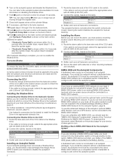
...of the internal input ports (port 1, port 2, port 3, or port 4) on the wiring harness. • There are not linked. Function N/A Ê N/A Ë Blue - Rx/A (+) Î NMEA 0183-Compatible Device Wire Function Power NMEA 0183 ground Rx/A (+) Rx/B (-) Tx/A (+) NOTE: When connecting a NMEA ...the chartplotter owner's manual for more information. • The ground wires on the included NMEA 0183 data cable. NMEA 2000 network (provides power to the helm control) À 12 Vdc power source Á Helm control  NMEA 0183-compatible device à Wire Helm Control Wire Color -...
...of the internal input ports (port 1, port 2, port 3, or port 4) on the wiring harness. • There are not linked. Function N/A Ê N/A Ë Blue - Rx/A (+) Î NMEA 0183-Compatible Device Wire Function Power NMEA 0183 ground Rx/A (+) Rx/B (-) Tx/A (+) NOTE: When connecting a NMEA ...the chartplotter owner's manual for more information. • The ground wires on the included NMEA 0183 data cable. NMEA 2000 network (provides power to the helm control) À 12 Vdc power source Á Helm control  NMEA 0183-compatible device à Wire Helm Control Wire Color -...
Installation Instructions
Page 11
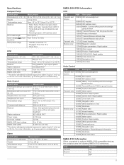
...gga 11 For more information, go to www.garmin.com/waterrating. Specifications Compact Pump Specification Dimensions (H × W × D) Weight Temperature range Material ECU cable length Input voltage the ECU) (from Main power usage Measurement 84.6 x 100.3 x 155...update 128259 Water speed 129025 Position: Rapid update 129029 GNSS position data 129283 Cross-track error 129284 Navigation data 129285 Navigation: Route/Waypoint information 130306 Wind data 130576 Small craft status NMEA 0183 Information When connected to optional NMEA 0183-compatible devices, the autopilot uses...
...gga 11 For more information, go to www.garmin.com/waterrating. Specifications Compact Pump Specification Dimensions (H × W × D) Weight Temperature range Material ECU cable length Input voltage the ECU) (from Main power usage Measurement 84.6 x 100.3 x 155...update 128259 Water speed 129025 Position: Rapid update 129029 GNSS position data 129283 Cross-track error 129284 Navigation data 129285 Navigation: Route/Waypoint information 130306 Wind data 130576 Small craft status NMEA 0183 Information When connected to optional NMEA 0183-compatible devices, the autopilot uses...

Installation Instructions
Page 12
... (sailboat only) The autopilot is no longer receiving navigation receiving valid navigation data. Garmin® and the Garmin logo are trademarks of Garmin Ltd. GHP™, GHC™, Reactor™, and Shadow Drive™ are trademarks of Garmin Ltd. NMEA®, NMEA 2000®, and the NMEA 2000 logo are trademarks of the National Marine Electronics Association. or...
... (sailboat only) The autopilot is no longer receiving navigation receiving valid navigation data. Garmin® and the Garmin logo are trademarks of Garmin Ltd. GHP™, GHC™, Reactor™, and Shadow Drive™ are trademarks of Garmin Ltd. NMEA®, NMEA 2000®, and the NMEA 2000 logo are trademarks of the National Marine Electronics Association. or...


