Manual/User Guide
Page 1
C141-E262 3-1 CHAPTER 3 Installation Conditions 3.1 Dimensions 3.2 Mounting 3.3 Connections with Host System This chapter gives the external dimensions, installation conditions, surface temperature conditions, cable connections, and switch settings of the hard disk drives.
C141-E262 3-1 CHAPTER 3 Installation Conditions 3.1 Dimensions 3.2 Mounting 3.3 Connections with Host System This chapter gives the external dimensions, installation conditions, surface temperature conditions, cable connections, and switch settings of the hard disk drives.
Manual/User Guide
Page 2
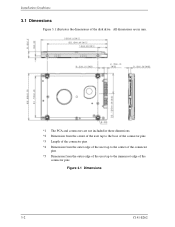
All dimensions are in mm. *1 The PCA and connectors are not included in these dimensions. *2 Dimension from the center of the user tap to the base of the connector pins *3 Length of the connector pins *4 Dimension from the outer edge of the user tap to the center of the connector pins *5 Dimension from the outer edge of the user tap to the innermost edge of the disk drive. Installation Conditions 3.1 Dimensions Figure 3.1 illustrates the dimensions of the connector pins Figure 3.1 Dimensions 3-2 C141-E262
All dimensions are in mm. *1 The PCA and connectors are not included in these dimensions. *2 Dimension from the center of the user tap to the base of the connector pins *3 Length of the connector pins *4 Dimension from the outer edge of the user tap to the center of the connector pins *5 Dimension from the outer edge of the user tap to the innermost edge of the disk drive. Installation Conditions 3.1 Dimensions Figure 3.1 illustrates the dimensions of the connector pins Figure 3.1 Dimensions 3-2 C141-E262
Manual/User Guide
Page 3
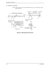
... specification in any direction. (2) Frame The MR head bias of the HDD disk enclosure (DE) is attached. When attaching the HDD to the system frame, do not allow the system frame to touch parts (cover and base) other than parts to Signal Ground (SG). 3.2 Mounting 3.2 Mounting For information on mounting, see the "FUJITSU 2.5-INCH HDD INTEGRATION GUIDANCE (C141-E144)." (1) Orientation The disk drives...
... specification in any direction. (2) Frame The MR head bias of the HDD disk enclosure (DE) is attached. When attaching the HDD to the system frame, do not allow the system frame to touch parts (cover and base) other than parts to Signal Ground (SG). 3.2 Mounting 3.2 Mounting For information on mounting, see the "FUJITSU 2.5-INCH HDD INTEGRATION GUIDANCE (C141-E144)." (1) Orientation The disk drives...
Manual/User Guide
Page 4
Bottom surface mounting DE 2 A Frame of system cabinet 2.5 2.5 2.5 Side surface 2.5 mounting PCA B Frame of system cabinet 3.0 or less Screw Details of mounting Note) These dimensions are recommended values; if it is not possible to satisfy them, contact us. Installation Conditions (3) Limitation of A 3.0 or less Screw Figure 3.2 Mounting frame structure 3-4 C141-E262
Bottom surface mounting DE 2 A Frame of system cabinet 2.5 2.5 2.5 Side surface 2.5 mounting PCA B Frame of system cabinet 3.0 or less Screw Details of mounting Note) These dimensions are recommended values; if it is not possible to satisfy them, contact us. Installation Conditions (3) Limitation of A 3.0 or less Screw Figure 3.2 Mounting frame structure 3-4 C141-E262
Manual/User Guide
Page 5
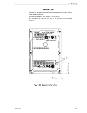
3.2 Mounting Because of breather C141-E262 3-5 Figure 3.3 Location of breather hole mounted to the HDD, do not allow this to block. Locating of Figure 3.3, at least, do not allow its around φ 3 to close during mounting. For breather hole of breather hole is shown as Figure 3.3.
3.2 Mounting Because of breather C141-E262 3-5 Figure 3.3 Location of breather hole mounted to the HDD, do not allow this to block. Locating of Figure 3.3, at least, do not allow its around φ 3 to close during mounting. For breather hole of breather hole is shown as Figure 3.3.
Manual/User Guide
Page 6
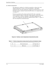
... the cabinet such that the PCA side, in particular, receives sufficient cooling. Measurement point Temperature 1 DE cover 60 °C max 3-6 C141-E262 Installation Conditions (4) Ambient temperature The temperature conditions for a disk drive mounted in a cabinet refer to prevent the DE surface cover temperature from the disk drive. Regardless of the DE. To check the cooling efficiency, measure the surface cover...
... the cabinet such that the PCA side, in particular, receives sufficient cooling. Measurement point Temperature 1 DE cover 60 °C max 3-6 C141-E262 Installation Conditions (4) Ambient temperature The temperature conditions for a disk drive mounted in a cabinet refer to prevent the DE surface cover temperature from the disk drive. Regardless of the DE. To check the cooling efficiency, measure the surface cover...
Manual/User Guide
Page 7
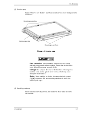
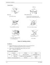
... the body ground (500 kΩ or greater). Ensure that the disk drive is not affected by the edges. (6) Handling cautions Please keep the following cautions, and handle the HDD under the safety environment. Mounting screw hole Cable connection Mounting screw hole Figure 3.5 Service area Data corruption: Avoid mounting the disk drive near strong magnetic sources such as loud speakers.
... the body ground (500 kΩ or greater). Ensure that the disk drive is not affected by the edges. (6) Handling cautions Please keep the following cautions, and handle the HDD under the safety environment. Mounting screw hole Cable connection Mounting screw hole Figure 3.5 Service area Data corruption: Avoid mounting the disk drive near strong magnetic sources such as loud speakers.
Manual/User Guide
Page 8
...impact when you use the driver of the screw strictly. ESD mat Shock absorbing mat Place the shock absorbing mat on the operation table, and place ESD mat on it. Do not drop. Recommended equipments ESD Shock Contents Wrist strap ESD mat Low shock driver Model JX-1200-...3056-8 SKY-8A (Color Seiden Mat) SS-6500 Maker SUMITOMO 3M Achilles HIOS 3-8 C141-E262 Do not place HDD vertically to avoid falling down. M3 0.49N • m (5 kgf • cm). - Installation Conditions - Do not hit HDD each other. Installation (1) Please use an electric driver. Do...
...impact when you use the driver of the screw strictly. ESD mat Shock absorbing mat Place the shock absorbing mat on the operation table, and place ESD mat on it. Do not drop. Recommended equipments ESD Shock Contents Wrist strap ESD mat Low shock driver Model JX-1200-...3056-8 SKY-8A (Color Seiden Mat) SS-6500 Maker SUMITOMO 3M Achilles HIOS 3-8 C141-E262 Do not place HDD vertically to avoid falling down. M3 0.49N • m (5 kgf • cm). - Installation Conditions - Do not hit HDD each other. Installation (1) Please use an electric driver. Do...
Manual/User Guide
Page 9
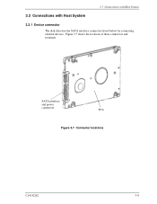
3.3 Connections with Host System 3.3 Connections with Host System 3.3.1 Device connector The disk drive has the SATA interface connectors listed below for connecting external devices. Figure 3.7 shows the locations of these connectors and terminals. SATA interface and power connectors PCA Figure 3.7 Connector locations C141-E262 3-9
3.3 Connections with Host System 3.3 Connections with Host System 3.3.1 Device connector The disk drive has the SATA interface connectors listed below for connecting external devices. Figure 3.7 shows the locations of these connectors and terminals. SATA interface and power connectors PCA Figure 3.7 Connector locations C141-E262 3-9
Manual/User Guide
Page 10
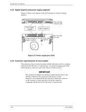
... the PCA side Figure 3.8 Power supply pins (CN1) 3.3.3 Connector specifications for mating with the disk drive must be compliant with the Serial ATA Revision 2.5 specification. 3-10 C141-E262 Installation Conditions 3.3.2 Signal segment and power supply segment Figure 3.8 shows each segment of the connection with the host system. The connection reliability per number of insertion/extractions varies with the condition of the SATA interface connector and pin numbers. For detail of host...
... the PCA side Figure 3.8 Power supply pins (CN1) 3.3.3 Connector specifications for mating with the disk drive must be compliant with the Serial ATA Revision 2.5 specification. 3-10 C141-E262 Installation Conditions 3.3.2 Signal segment and power supply segment Figure 3.8 shows each segment of the connection with the host system. The connection reliability per number of insertion/extractions varies with the condition of the SATA interface connector and pin numbers. For detail of host...
Manual/User Guide
Page 11
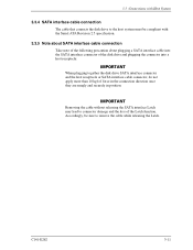
... SATA interface Latch may lead to remove the cable while releasing the Latch. C141-E262 3-11 3.3 Connections with Host System 3.3.4 SATA interface cable connection The cable that connects the disk drive to the host system must be sure to connector damage and the loss of force in the connection direction once they are snugly and securely in position. Accordingly, be compliant with the Serial ATA Revision 2.5 specification. 3.3.5 Note about SATA interface cable connection...
... SATA interface Latch may lead to remove the cable while releasing the Latch. C141-E262 3-11 3.3 Connections with Host System 3.3.4 SATA interface cable connection The cable that connects the disk drive to the host system must be sure to connector damage and the loss of force in the connection direction once they are snugly and securely in position. Accordingly, be compliant with the Serial ATA Revision 2.5 specification. 3.3.5 Note about SATA interface cable connection...


