Manual/User Guide
Page 3
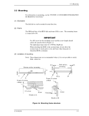
The tightening torque must be mounted in Figure 3.2. 3.2 Mounting 3.2 Mounting For information on mounting, see the "FUJITSU 2.5-INCH HDD INTEGRATION GUIDANCE (C141-E144)." (1) Orientation The disk drives can be 0.49N•m (5kgf•cm). The mounting frame is not possible to satisfy them, contact... mounting Note) These dimensions are recommended values; Use M3 screw for the mounting screw and the screw length should satisfy the specification in any direction. (2) Frame The MR head bias of the HDD disk enclosure (DE) is attached. (3) Limitation of B Figure 3.2...
The tightening torque must be mounted in Figure 3.2. 3.2 Mounting 3.2 Mounting For information on mounting, see the "FUJITSU 2.5-INCH HDD INTEGRATION GUIDANCE (C141-E144)." (1) Orientation The disk drives can be 0.49N•m (5kgf•cm). The mounting frame is not possible to satisfy them, contact... mounting Note) These dimensions are recommended values; Use M3 screw for the mounting screw and the screw length should satisfy the specification in any direction. (2) Frame The MR head bias of the HDD disk enclosure (DE) is attached. (3) Limitation of B Figure 3.2...
Manual/User Guide
Page 9
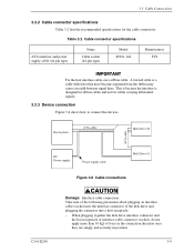
... plugging an interface cable (socket) into the interface connector of the disk drive and plugging the connector into a host receptacle: − When plugging together the disk drive interface connector and the host receptacle or interface cable connector (socket), do ... is because the interface is designed for ribbon cables and not for the cable connectors. 3.3 Cable Connections 3.3.2 Cable connector specifications Table 3.2 lists the recommended specifications for cables carrying differential signals. 3.3.3 Device connection Figure 3.8 shows how to connect the devices. A twisted cable or ...
... plugging an interface cable (socket) into the interface connector of the disk drive and plugging the connector into a host receptacle: − When plugging together the disk drive interface connector and the host receptacle or interface cable connector (socket), do ... is because the interface is designed for ribbon cables and not for the cable connectors. 3.3 Cable Connections 3.3.2 Cable connector specifications Table 3.2 lists the recommended specifications for cables carrying differential signals. 3.3.3 Device connection Figure 3.8 shows how to connect the devices. A twisted cable or ...
