Manual/User Guide
Page 1
C141-E144 C141-E250 3-1 For information about handling this hard disk drive and the system installation procedure, refer to the following Integration Guide. CHAPTER 3 Installation Conditions 3.1 Dimensions 3.2 Mounting 3.3 Cable Connections 3.4 Jumper Settings This chapter gives the external dimensions, installation conditions, surface temperature conditions, cable connections, and switch settings of the hard disk drives.
C141-E144 C141-E250 3-1 For information about handling this hard disk drive and the system installation procedure, refer to the following Integration Guide. CHAPTER 3 Installation Conditions 3.1 Dimensions 3.2 Mounting 3.3 Cable Connections 3.4 Jumper Settings This chapter gives the external dimensions, installation conditions, surface temperature conditions, cable connections, and switch settings of the hard disk drives.
Manual/User Guide
Page 2
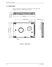
All dimensions are in mm. Installation Conditions 3.1 Dimensions Figure 3.1 illustrates the dimensions of the disk drive and positions of the mounting screw holes. Figure 3.1 Dimensions 3-2 C141-E250
All dimensions are in mm. Installation Conditions 3.1 Dimensions Figure 3.1 illustrates the dimensions of the disk drive and positions of the mounting screw holes. Figure 3.1 Dimensions 3-2 C141-E250
Manual/User Guide
Page 3
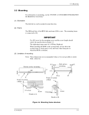
... the specification in any direction. (2) Frame The MR head bias of the HDD disk enclosure (DE) is connected to satisfy them, contact us. The tightening torque must be mounted in Figure 3.2. The mounting frame is zero. if it is attached. (3) Limitation of B Figure 3.2 Mounting frame structure C141-E250 3-3 3.2 Mounting 3.2 Mounting For information on mounting, see the "FUJITSU 2.5-INCH HDD...
... the specification in any direction. (2) Frame The MR head bias of the HDD disk enclosure (DE) is connected to satisfy them, contact us. The tightening torque must be mounted in Figure 3.2. The mounting frame is zero. if it is attached. (3) Limitation of B Figure 3.2 Mounting frame structure C141-E250 3-3 3.2 Mounting 3.2 Mounting For information on mounting, see the "FUJITSU 2.5-INCH HDD...
Manual/User Guide
Page 4
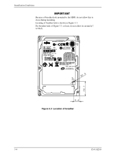
Figure 3.3 Location of breather hole is shown as Figure 3.3. Locating of breather 3-4 C141-E250 Installation Conditions Because of breather hole mounted to the HDD, do not allow this to block. For breather hole of Figure 3.3, at least, do not allow its around φ 3 to close during mounting.
Figure 3.3 Location of breather hole is shown as Figure 3.3. Locating of breather 3-4 C141-E250 Installation Conditions Because of breather hole mounted to the HDD, do not allow this to block. For breather hole of Figure 3.3, at least, do not allow its around φ 3 to close during mounting.
Manual/User Guide
Page 5
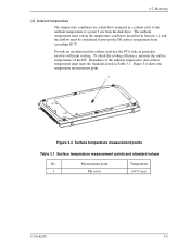
... standard values No. Regardless of the DE. Measurement point Temperature 1 DE cover 60 °C max C141-E250 3-5 The ambient temperature must satisfy the temperature conditions described in Section 1.4, and the airflow must meet the standards listed in particular, receives sufficient cooling. 3.2 Mounting (4) Ambient temperature The temperature conditions for a disk drive mounted in a cabinet refer to prevent the DE surface...
... standard values No. Regardless of the DE. Measurement point Temperature 1 DE cover 60 °C max C141-E250 3-5 The ambient temperature must satisfy the temperature conditions described in Section 1.4, and the airflow must meet the standards listed in particular, receives sufficient cooling. 3.2 Mounting (4) Ambient temperature The temperature conditions for a disk drive mounted in a cabinet refer to prevent the DE surface...
Manual/User Guide
Page 6
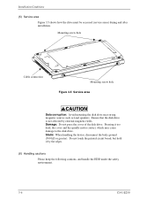
Pressing it by external magnetic fields. Mounting screw hole Cable connection Mounting screw hole Figure 3.5 Service area Data corruption: Avoid mounting the disk drive near strong magnetic sources such as loud speakers. Ensure that the disk drive is not affected by the edges. (6) Handling cautions Please keep the following cautions, and handle the HDD under the safety environment. 3-6 C141-E250 Do...
Pressing it by external magnetic fields. Mounting screw hole Cable connection Mounting screw hole Figure 3.5 Service area Data corruption: Avoid mounting the disk drive near strong magnetic sources such as loud speakers. Ensure that the disk drive is not affected by the edges. (6) Handling cautions Please keep the following cautions, and handle the HDD under the safety environment. 3-6 C141-E250 Do...
Manual/User Guide
Page 7
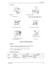
... mat Shock absorbing mat Place the shock absorbing mat on the operation table, and place ESD mat on it. Installation (1) Please use the driver of the screw strictly. Do not hit HDD each other. Recommended equipments ESD Shock Contents Wrist strap ESD mat Low shock driver Model JX-1200-3056-8 SKY-8A (Color Seiden Mat) SS-6500...
... mat Shock absorbing mat Place the shock absorbing mat on the operation table, and place ESD mat on it. Installation (1) Please use the driver of the screw strictly. Do not hit HDD each other. Recommended equipments ESD Shock Contents Wrist strap ESD mat Low shock driver Model JX-1200-3056-8 SKY-8A (Color Seiden Mat) SS-6500...
Manual/User Guide
Page 8
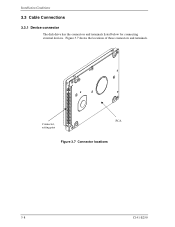
Figure 3.7 shows the locations of these connectors and terminals. Connector, setting pins PCA Figure 3.7 Connector locations 3-8 C141-E250 Installation Conditions 3.3 Cable Connections 3.3.1 Device connector The disk drive has the connectors and terminals listed below for connecting external devices.
Figure 3.7 shows the locations of these connectors and terminals. Connector, setting pins PCA Figure 3.7 Connector locations 3-8 C141-E250 Installation Conditions 3.3 Cable Connections 3.3.1 Device connector The disk drive has the connectors and terminals listed below for connecting external devices.
Manual/User Guide
Page 9
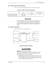
... the disk drive interface connector and the host receptacle or interface cable connector (socket), do not apply more than 10 kgf of force in the connection direction once they are snugly and securely in position. 3-9 A twisted cable or a cable with wires that have become separated from the ribbon may cause crosstalk between signal lines. Table 3.2 Cable connector specifications ATA interface and power supply cable (44-pin type) Name Cable socket (44-pin type) Model 89361...
... the disk drive interface connector and the host receptacle or interface cable connector (socket), do not apply more than 10 kgf of force in the connection direction once they are snugly and securely in position. 3-9 A twisted cable or a cable with wires that have become separated from the ribbon may cause crosstalk between signal lines. Table 3.2 Cable connector specifications ATA interface and power supply cable (44-pin type) Name Cable socket (44-pin type) Model 89361...
Manual/User Guide
Page 10
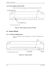
Figure 3.10 Jumper location 3-10 C141-E250 Figure 3.9 Power supply connector pins (CN1) 3.4 Jumper Settings 3.4.1 Location of setting jumpers Figure 3.10 shows the location of the power supply connector (CN1). Installation Conditions 3.3.4 Power supply connector (CN1) Figure 3.9 shows the pin assignment of the jumpers to select drive configuration and functions.
Figure 3.10 Jumper location 3-10 C141-E250 Figure 3.9 Power supply connector pins (CN1) 3.4 Jumper Settings 3.4.1 Location of setting jumpers Figure 3.10 shows the location of the power supply connector (CN1). Installation Conditions 3.3.4 Power supply connector (CN1) Figure 3.9 shows the pin assignment of the jumpers to select drive configuration and functions.
Manual/User Guide
Page 11
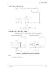
C141-E250 3-11 Open Figure 3.11 Factory default setting 3.4.3 Master drive-slave drive setting Master drive (disk drive #0) or slave drive (disk drive #1) is selected. Open 1 CA 2 DB Open (a) Master drive 1 CA Open Short 2 DB (b) Slave drive Figure 3.12 Jumper setting of master or slave drive Note: Pins A and C should be open. 3.4 Jumper Settings 3.4.2 Factory default setting Figure 3.11 shows the default setting position at the factory.
C141-E250 3-11 Open Figure 3.11 Factory default setting 3.4.3 Master drive-slave drive setting Master drive (disk drive #0) or slave drive (disk drive #1) is selected. Open 1 CA 2 DB Open (a) Master drive 1 CA Open Short 2 DB (b) Slave drive Figure 3.12 Jumper setting of master or slave drive Note: Pins A and C should be open. 3.4 Jumper Settings 3.4.2 Factory default setting Figure 3.11 shows the default setting position at the factory.
Manual/User Guide
Page 12
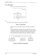
...) of cable selection using unique interface cables. At this time, the CSEL of cable select 3-12 C141-E250 The drive is identified as a slave drive. drive drive Figure 3.14 Example (1) of the slave drive does not have a conductor. Installation Conditions 3.4.4 CSEL setting Figure 3.13 shows the cable select (CSEL) setting. Open 1 CA 2 DB Short Note: The CSEL setting is set to high level. The drive is identified as a master drive. Thus, since the slave drive is not connected to...
...) of cable selection using unique interface cables. At this time, the CSEL of cable select 3-12 C141-E250 The drive is identified as a slave drive. drive drive Figure 3.14 Example (1) of the slave drive does not have a conductor. Installation Conditions 3.4.4 CSEL setting Figure 3.13 shows the cable select (CSEL) setting. Open 1 CA 2 DB Short Note: The CSEL setting is set to high level. The drive is identified as a master drive. Thus, since the slave drive is not connected to...
Manual/User Guide
Page 13
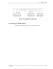
C141-E250 3-13 3.4 Jumper Settings drive Figure 3.15 Example (2) of cable select drive 3.4.5 Power up in standby setting When pin C is grounded, the drive does not spin up at power on.
C141-E250 3-13 3.4 Jumper Settings drive Figure 3.15 Example (2) of cable select drive 3.4.5 Power up in standby setting When pin C is grounded, the drive does not spin up at power on.


