Manual/User Guide
Page 1
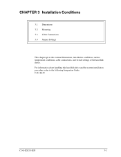
C141-E144 C141-E202-01EN 3-1 CHAPTER 3 Installation Conditions 3.1 Dimensions 3.2 Mounting 3.3 Cable Connections 3.4 Jumper Settings This chapter gives the external dimensions, installation conditions, surface temperature conditions, cable connections, and switch settings of the hard disk drives. For information about handling this hard disk drive and the system installation procedure, refer to the following Integration Guide.
C141-E144 C141-E202-01EN 3-1 CHAPTER 3 Installation Conditions 3.1 Dimensions 3.2 Mounting 3.3 Cable Connections 3.4 Jumper Settings This chapter gives the external dimensions, installation conditions, surface temperature conditions, cable connections, and switch settings of the hard disk drives. For information about handling this hard disk drive and the system installation procedure, refer to the following Integration Guide.
Manual/User Guide
Page 7
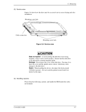
...body ground (500 kΩ or greater). Mounting screw hole Cable connection Mounting screw hole Figure 3.6 Service area Data corruption: Avoid mounting the disk drive near strong magnetic sources such as loud speakers. Ensure that the disk drive is not affected by the edges. (6) Handling cautions Please keep... the following cautions, and handle the HDD under the safety environment. Do not touch the printed circuit board, but hold it too hard, the cover and the spindle motor...
...body ground (500 kΩ or greater). Mounting screw hole Cable connection Mounting screw hole Figure 3.6 Service area Data corruption: Avoid mounting the disk drive near strong magnetic sources such as loud speakers. Ensure that the disk drive is not affected by the edges. (6) Handling cautions Please keep... the following cautions, and handle the HDD under the safety environment. Do not touch the printed circuit board, but hold it too hard, the cover and the spindle motor...
Manual/User Guide
Page 9
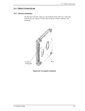
3.3 Cable Connections 3.3 Cable Connections 3.3.1 Device connector The disk drive has the connectors and terminals listed below for connecting external devices. Figure 3.8 shows the locations of these connectors and terminals. Connector, PCA setting pins Figure 3.8 Connector locations C141-E202-01EN 3-9
3.3 Cable Connections 3.3 Cable Connections 3.3.1 Device connector The disk drive has the connectors and terminals listed below for connecting external devices. Figure 3.8 shows the locations of these connectors and terminals. Connector, PCA setting pins Figure 3.8 Connector locations C141-E202-01EN 3-9
Manual/User Guide
Page 10
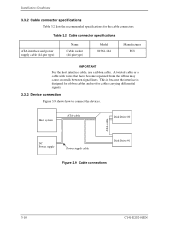
... the interface is designed for ribbon cables and not for the cable connectors. Installation Conditions 3.3.2 Cable connector specifications Table 3.2 lists the recommended specifications for cables carrying differential signals. 3.3.3 Device connection Figure 3.9 shows how to connect the devices. Host system ATA-cable Disk Drive #0 ATA-cable DC Power supply Power supply cable Disk Drive #1 Figure 3.9 Cable connections 3-10 C141-E202-01EN
... the interface is designed for ribbon cables and not for the cable connectors. Installation Conditions 3.3.2 Cable connector specifications Table 3.2 lists the recommended specifications for cables carrying differential signals. 3.3.3 Device connection Figure 3.9 shows how to connect the devices. Host system ATA-cable Disk Drive #0 ATA-cable DC Power supply Power supply cable Disk Drive #1 Figure 3.9 Cable connections 3-10 C141-E202-01EN
Manual/User Guide
Page 13
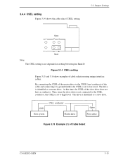
... is set to high level. The drive is identified as a slave drive. By connecting the CSEL of the master drive to the CSEL Line (conducer) of cable selection using unique interface cables. The drive is identified as a master drive. 3.4.4 CSEL setting Figure 3.14 shows the cable select (CSEL) setting. 3.4 Jumper ...Short Note: The CSEL setting is set to low level. drive drive Figure 3.15 Example (1) of the slave drive does not have a conductor. Figure 3.14 CSEL setting Figure 3.15 and 3.16 show examples of the cable and connecting it to ground further, the CSEL is not ...
... is set to high level. The drive is identified as a slave drive. By connecting the CSEL of the master drive to the CSEL Line (conducer) of cable selection using unique interface cables. The drive is identified as a master drive. 3.4.4 CSEL setting Figure 3.14 shows the cable select (CSEL) setting. 3.4 Jumper ...Short Note: The CSEL setting is set to low level. drive drive Figure 3.15 Example (1) of the slave drive does not have a conductor. Figure 3.14 CSEL setting Figure 3.15 and 3.16 show examples of the cable and connecting it to ground further, the CSEL is not ...
Manual/User Guide
Page 14
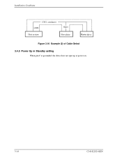
Installation Conditions drive drive Figure 3.16 Example (2) of Cable Select 3.4.5 Power Up in Standby setting When pin C is grounded, the drive does not spin up at power on. 3-14 C141-E202-01EN
Installation Conditions drive drive Figure 3.16 Example (2) of Cable Select 3.4.5 Power Up in Standby setting When pin C is grounded, the drive does not spin up at power on. 3-14 C141-E202-01EN