
Manual/User Guide
Page 5
... 2 Device Configuration This chapter describes the internal configurations of the MHN Series and the configuration of the drives and explains in detail how to incorporate the drives into user systems. This manual assumes that is compatible with the ATA interface. CHAPTER 6 Operations This ...This manual describes the specifications and functions of the systems in this manual. Preface This manual describes the MHN Series, 2.5-inch hard disk drives. Terminology This section explains the special terminology used in this manual: Overview of Manual CHAPTER 1 Device Overview This chapter gives ...
... 2 Device Configuration This chapter describes the internal configurations of the MHN Series and the configuration of the drives and explains in detail how to incorporate the drives into user systems. This manual assumes that is compatible with the ATA interface. CHAPTER 6 Operations This ...This manual describes the specifications and functions of the systems in this manual. Preface This manual describes the MHN Series, 2.5-inch hard disk drives. Terminology This section explains the special terminology used in this manual: Overview of Manual CHAPTER 1 Device Overview This chapter gives ...
Manual/User Guide
Page 6
... the sheet. Attention Please forward any comments you may occur if the user does not perform the procedure correctly. This indicates information that the disk drive is centered, followed below by external magnetic fields. Ensure that could result in the "Important Alert Items." An alert message consists of an alert symbol... text, the alert signal is not affected by the indented message. Operating Environment This product is an example: (Example) Data corruption: Avoid mounting the disk drive near strong magnetic sources such as loud speakers.
... the sheet. Attention Please forward any comments you may occur if the user does not perform the procedure correctly. This indicates information that the disk drive is centered, followed below by external magnetic fields. Ensure that could result in the "Important Alert Items." An alert message consists of an alert symbol... text, the alert signal is not affected by the indented message. Operating Environment This product is an example: (Example) Data corruption: Avoid mounting the disk drive near strong magnetic sources such as loud speakers.
Manual/User Guide
Page 7
Preface Liability Exception "Disk drive defects" refers to defects that involve adjustment, repair, or replacement. C141-E120-02EN iii Fujitsu is not liable for any other disk drive defects, such as those caused by user misoperation or mishandling, inappropriate operating environments, defects in the power supply or cable, problems of the host system, or other causes outside the disk drive.
Preface Liability Exception "Disk drive defects" refers to defects that involve adjustment, repair, or replacement. C141-E120-02EN iii Fujitsu is not liable for any other disk drive defects, such as those caused by user misoperation or mishandling, inappropriate operating environments, defects in the power supply or cable, problems of the host system, or other causes outside the disk drive.
Manual/User Guide
Page 9
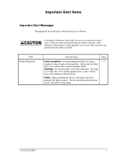
... not affected by the edges. Pressing it by external magnetic fields. Do not touch the printed circuit board, but hold it too hard, the cover and the spindle motor contact, which may occur if the user does not perform the procedure correctly. Also, damage to the ...product or other property, may cause damage to the disk drive. Task Normal Operation Alert message Page Data corruption: Avoid mounting the disk near strong 3-7 magnetic sources such as follows: A hazardous situation could result ...
... not affected by the edges. Pressing it by external magnetic fields. Do not touch the printed circuit board, but hold it too hard, the cover and the spindle motor contact, which may occur if the user does not perform the procedure correctly. Also, damage to the ...product or other property, may cause damage to the disk drive. Task Normal Operation Alert message Page Data corruption: Avoid mounting the disk near strong 3-7 magnetic sources such as follows: A hazardous situation could result ...
Manual/User Guide
Page 11
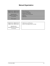
Manual Organization MHN2300AT, MHN2200AT, MHN2150AT, MHN2100AT DISK DRIVES PRODUCT MANUAL (C141-E120) • Device Overview • Device Configuration • Installation Conditions • Theory of Device Operation • Interface • Operations MHN2300AT, MHN2200AT, MHN2150AT, MHN2100AT DISK DRIVES MAINTENANCE MANUAL (C141-E120) • Maintenance and Diagnosis • Removal and Replacement Procedure C141-E120-02EN vii
Manual Organization MHN2300AT, MHN2200AT, MHN2150AT, MHN2100AT DISK DRIVES PRODUCT MANUAL (C141-E120) • Device Overview • Device Configuration • Installation Conditions • Theory of Device Operation • Interface • Operations MHN2300AT, MHN2200AT, MHN2150AT, MHN2100AT DISK DRIVES MAINTENANCE MANUAL (C141-E120) • Maintenance and Diagnosis • Removal and Replacement Procedure C141-E120-02EN vii
Manual/User Guide
Page 14
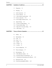
... 3-9 3.3.2 Cable connector specifications 3-10 3.3.3 Device connection 3-10 3.3.4 Power supply connector (CN1) 3-11 3.4 Jumper Settings 3-11 3.4.1 Location of setting jumpers 3-11 3.4.2 Factory default setting 3-12 3.4.3 Master drive-slave drive setting 3-12 3.4.4 CSEL setting 3-13 CHAPTER 4 Theory of Device Operation 4-1 4.1 Outline 4-2 4.2 Subassemblies 4-2 4.2.1 Disk 4-2 4.2.2 Head 4-2 4.2.3 Spindle 4-3 4.2.4 Actuator 4-3 4.2.5 Air filter 4-3 4.3 Circuit Configuration 4-4 4.4 Power-on Sequence 4-7 4.5 Self...
... 3-9 3.3.2 Cable connector specifications 3-10 3.3.3 Device connection 3-10 3.3.4 Power supply connector (CN1) 3-11 3.4 Jumper Settings 3-11 3.4.1 Location of setting jumpers 3-11 3.4.2 Factory default setting 3-12 3.4.3 Master drive-slave drive setting 3-12 3.4.4 CSEL setting 3-13 CHAPTER 4 Theory of Device Operation 4-1 4.1 Outline 4-2 4.2 Subassemblies 4-2 4.2.1 Disk 4-2 4.2.2 Head 4-2 4.2.3 Spindle 4-3 4.2.4 Actuator 4-3 4.2.5 Air filter 4-3 4.3 Circuit Configuration 4-4 4.4 Power-on Sequence 4-7 4.5 Self...
Manual/User Guide
Page 18
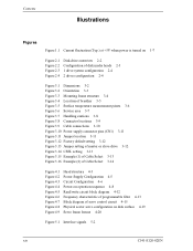
... Power supply connector pins (CN1) 3-11 Figure 3.11 Jumper location 3-11 Figure 3.12 Factory default setting 3-12 Figure 3.13 Jumper setting of master or slave drive 3-12 Figure 3.14 CSEL setting 3-13 Figure 3.15 Example (1) of Cable Select 3-13 Figure 3.16 Example (2) of Cable Select 3-14 Figure 4.1 Figure 4.2 Figure 4.3 Figure 4.4 Figure... 4-12 Frequency characteristic of programmable filter 4-13 Block diagram of servo control circuit 4-15 Physical sector servo configuration on disk surface 4-19 Servo frame format 4-20 Figure 5.1 Interface signals 5-2 xiv C141-E120-02EN
... Power supply connector pins (CN1) 3-11 Figure 3.11 Jumper location 3-11 Figure 3.12 Factory default setting 3-12 Figure 3.13 Jumper setting of master or slave drive 3-12 Figure 3.14 CSEL setting 3-13 Figure 3.15 Example (1) of Cable Select 3-13 Figure 3.16 Example (2) of Cable Select 3-14 Figure 4.1 Figure 4.2 Figure 4.3 Figure 4.4 Figure... 4-12 Frequency characteristic of programmable filter 4-13 Block diagram of servo control circuit 4-15 Physical sector servo configuration on disk surface 4-19 Servo frame format 4-20 Figure 5.1 Interface signals 5-2 xiv C141-E120-02EN
Manual/User Guide
Page 21
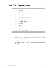
The MHN Series are 2.5-inch hard disk drives with built-in this chapter, and specifications and power requirement are described. These disk drives use the AT-bus hard disk interface protocol and are compact and reliable. C141-E120-02EN 1-1 CHAPTER 1 Device Overview 1.1 Features 1.2 Device Specifications 1.3 Power Requirements 1.4 Environmental Specifications 1.5 Acoustic Noise 1.6 Shock and Vibration 1.7 Reliability 1.8 Error Rate 1.9 Media Defects 1.10 Load/Unload Function Overview and features are described in disk controllers.
The MHN Series are 2.5-inch hard disk drives with built-in this chapter, and specifications and power requirement are described. These disk drives use the AT-bus hard disk interface protocol and are compact and reliable. C141-E120-02EN 1-1 CHAPTER 1 Device Overview 1.1 Features 1.2 Device Specifications 1.3 Power Requirements 1.4 Environmental Specifications 1.5 Acoustic Noise 1.6 Shock and Vibration 1.7 Reliability 1.8 Error Rate 1.9 Media Defects 1.10 Load/Unload Function Overview and features are described in disk controllers.
Manual/User Guide
Page 22
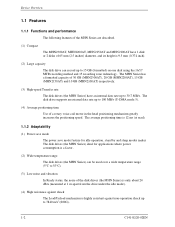
The MHN Series has a formatted capacity of 30 GB (MHN2300AT), 20 GB (MHN2200AT), 15 GB (MHN2150AT) and 10 GB (MHN2100AT) respectively. (3) High-speed Transfer rate The disk drives (the MHN Series) have 1 disk or 2 disks of 65 mm (2.5 inches) diameter, and its height is highly resistant against non-operation shock up to 7840 m/...
The MHN Series has a formatted capacity of 30 GB (MHN2300AT), 20 GB (MHN2200AT), 15 GB (MHN2150AT) and 10 GB (MHN2100AT) respectively. (3) High-speed Transfer rate The disk drives (the MHN Series) have 1 disk or 2 disks of 65 mm (2.5 inches) diameter, and its height is highly resistant against non-operation shock up to 7840 m/...

Manual/User Guide
Page 23
..., if the read ahead data corresponds to the data requested by ECC If a recoverable error occurs, the disk drives (the MHN Series) themselves attempt error recovery. Drive 0 is a master device, drive 1 is a slave device. (5) Error correction and retry by the next read ahead operation). Executing the diagnostic ...ahead cache system described in item (3) and the write cache described in the buffer can be transferred instead. (4) Master/slave The disk drives (the MHN Series) can be connected to the disk media. In combination with the read command would normally cause another disk access....
..., if the read ahead data corresponds to the data requested by ECC If a recoverable error occurs, the disk drives (the MHN Series) themselves attempt error recovery. Drive 0 is a master device, drive 1 is a slave device. (5) Error correction and retry by the next read ahead operation). Executing the diagnostic ...ahead cache system described in item (3) and the write cache described in the buffer can be transferred instead. (4) Master/slave The disk drives (the MHN Series) can be connected to the disk media. In combination with the read command would normally cause another disk access....
Manual/User Guide
Page 24
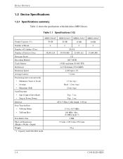
... ×70.0 mm Weight 98 g *1: Capacity under the LBA mode. 1-4 C141-E120-02EN Table 1.1 Specifications (1/2) MHN2300AT MHN2200AT MHN2150AT MHN2100AT Format Capacity (*1) 30 GB 20 GB 15 GB 10 GB Number of Heads 4 3 2 2 Number of Cylinders (User) 28,416 Number of the disk drives (MHN Series). Cable length: 0.46 m) Data Transfer Rate • To/From Media 17.4 to...
... ×70.0 mm Weight 98 g *1: Capacity under the LBA mode. 1-4 C141-E120-02EN Table 1.1 Specifications (1/2) MHN2300AT MHN2200AT MHN2150AT MHN2100AT Format Capacity (*1) 30 GB 20 GB 15 GB 10 GB Number of Heads 4 3 2 2 Number of Cylinders (User) 28,416 Number of the disk drives (MHN Series). Cable length: 0.46 m) Data Transfer Rate • To/From Media 17.4 to...
Manual/User Guide
Page 28
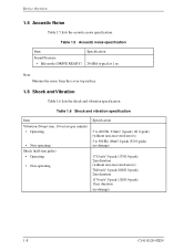
... 0-peak) 2ms duration 1176 m/s2 0-peak (120G 0-peak) 11ms duration (no damage) 1-8 C141-E120-02EN Table 1.5 Acoustic noise specification Item Sound Pressure • Idle mode (DRIVE READY) Specification 24 dBA typical at 1 m Note: Measure the noise from the cover top surface. 1.6 Shock and Vibration Table 1.6 lists the shock and vibration specification.
... 0-peak) 2ms duration 1176 m/s2 0-peak (120G 0-peak) 11ms duration (no damage) 1-8 C141-E120-02EN Table 1.5 Acoustic noise specification Item Sound Pressure • Idle mode (DRIVE READY) Specification 24 dBA typical at 1 m Note: Measure the noise from the cover top surface. 1.6 Shock and Vibration Table 1.6 lists the shock and vibration specification.
Manual/User Guide
Page 29
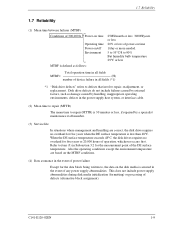
... (4) Data assurance in the event of power failure Except for five years or 20,000 hours of operation, whichever occurs first. When the DE surface temperature exceeds 48°C, the disk drives requires no overhaul for the measurement point of defects (alternative block assignment). This does...factors, such as follows: Total operation time in all fields MTBF= (H) number of device failure in all fields (*1) *1 "Disk drive defects" refers to defects that involve repair, readjustment, or replacement. Also the operating conditions except the environment temperature are correct, the disk...
... (4) Data assurance in the event of power failure Except for five years or 20,000 hours of operation, whichever occurs first. When the DE surface temperature exceeds 48°C, the disk drives requires no overhaul for the measurement point of defects (alternative block assignment). This does...factors, such as follows: Total operation time in all fields MTBF= (H) number of device failure in all fields (*1) *1 "Disk drive defects" refers to defects that involve repair, readjustment, or replacement. Also the operating conditions except the environment temperature are correct, the disk...
Manual/User Guide
Page 30
...evenly distributed on the disk and unloads the head from the factory (low level format). The user need not be recovered by the disk drive. Device Overview 1.8 Error Rate Known defects, for which alternative blocks can be assigned, are not included in 107 seek operations. 1.9 Media...and include read retries of drive without user's retry and ECC corrections shall occur no more than 10 times in the error rate count below. The product supports a minimum of 1014 bits. Thus, the hosts see a defect-free devices. Alternate sectors are executed. • Hard Reset • Standby &#...
...evenly distributed on the disk and unloads the head from the factory (low level format). The user need not be recovered by the disk drive. Device Overview 1.8 Error Rate Known defects, for which alternative blocks can be assigned, are not included in 107 seek operations. 1.9 Media...and include read retries of drive without user's retry and ECC corrections shall occur no more than 10 times in the error rate count below. The product supports a minimum of 1014 bits. Thus, the hosts see a defect-free devices. Alternate sectors are executed. • Hard Reset • Standby &#...
Manual/User Guide
Page 33
CHAPTER 2 Device Configuration 2.1 Device Configuration 2.2 System Configuration This chapter describes the internal configurations of the hard disk drives and the configuration of the systems in which they operate. C141-E120-02EN 2-1
CHAPTER 2 Device Configuration 2.1 Device Configuration 2.2 System Configuration This chapter describes the internal configurations of the hard disk drives and the configuration of the systems in which they operate. C141-E120-02EN 2-1

Manual/User Guide
Page 34
...surface, servo information necessary for controlling positioning and read /write preamplifier, and controller PCA. MHN Series (1) Disk (2) Head Figure 2.1 Disk drive outerview The outer diameter of while the disk is not rotating and loads on the disk when the disk starts. The head unloads the ...disk out of the disk is 20 mm. Device Configuration 2.1 Device Configuration Figure 2.1 shows the disk drive. Figure 2.2 illustrates the configuration of the disks and heads of the load/unload (L/UL) type. MHN2300AT: 2 ...
...surface, servo information necessary for controlling positioning and read /write preamplifier, and controller PCA. MHN Series (1) Disk (2) Head Figure 2.1 Disk drive outerview The outer diameter of while the disk is not rotating and loads on the disk when the disk starts. The head unloads the ...disk out of the disk is 20 mm. Device Configuration 2.1 Device Configuration Figure 2.1 shows the disk drive. Figure 2.2 illustrates the configuration of the disks and heads of the load/unload (L/UL) type. MHN2300AT: 2 ...

Manual/User Guide
Page 35
Head 3 2 1 0 MHN2300AT Head 3 2 1 0 2.1 Device Configuration Head 1 0 MHN2200AT (Either of head 0 or head 3 is mounted.) MHN2150AT MHN2100AT Figure 2.2 Configuration of the air within the disk enclosure. (6) Read/write circuit The read/write circuit.... It improves data reliability by preventing errors caused by external noise. (7) Controller circuit The controller circuit consists of the disk and is fixed by a direct drive Hall-less DC motor. (4) Actuator The actuator uses a revolving voice coil motor (VCM) structure which consumes low power and generates very little heat. If ...
Head 3 2 1 0 MHN2300AT Head 3 2 1 0 2.1 Device Configuration Head 1 0 MHN2200AT (Either of head 0 or head 3 is mounted.) MHN2150AT MHN2100AT Figure 2.2 Configuration of the air within the disk enclosure. (6) Read/write circuit The read/write circuit.... It improves data reliability by preventing errors caused by external noise. (7) Controller circuit The controller circuit consists of the disk and is fixed by a direct drive Hall-less DC motor. (4) Actuator The actuator uses a revolving voice coil motor (VCM) structure which consumes low power and generates very little heat. If ...

Manual/User Guide
Page 36
... 4 transfer at 16.6 MB/s, Multiword DMA mode 2 transfer at 16.6 MB/s and also U-DMA mode 5 transfer at 100 MB/s. 2.2.2 1 drive connection MHN2300AT MHNC2023020AT MMHHNC22014500AATT MHN2100AT Figure 2.3 1 drive system configuration 2.2.3 2 drives connection (Host adaptor) MHN2300AT MMHHNC22023020AATT MMHHNC22014500AATT MHN2100AT MHN2300AT MMMMMMMMHHHHHHHHNNNGHHCC22222222211100000500633400024220AAAAAAAATTTTTTTT Note: When the drive that is not conformed to ATA is connected to the disk...
... 4 transfer at 16.6 MB/s, Multiword DMA mode 2 transfer at 16.6 MB/s and also U-DMA mode 5 transfer at 100 MB/s. 2.2.2 1 drive connection MHN2300AT MHNC2023020AT MMHHNC22014500AATT MHN2100AT Figure 2.3 1 drive system configuration 2.2.3 2 drives connection (Host adaptor) MHN2300AT MMHHNC22023020AATT MMHHNC22014500AATT MHN2100AT MHN2300AT MMMMMMMMHHHHHHHHNNNGHHCC22222222211100000500633400024220AAAAAAAATTTTTTTT Note: When the drive that is not conformed to ATA is connected to the disk...
Manual/User Guide
Page 37
... of the signal lines including the HA and cable does not exceed the ATA-5 standard, and the cable length between the HA and the disk drive may be made it is necessary that could be as short as possible. Thus, it the cause of the signal lines (AT bus) between the... HA and the disk drive should be contacted with the spindle motor. C141-E120-02EN 2-5 At high speed data transfer (PIO mode 4 or DMA mode 2 U-DMA mode 5), occurrence of ringing...
... of the signal lines including the HA and cable does not exceed the ATA-5 standard, and the cable length between the HA and the disk drive may be made it is necessary that could be as short as possible. Thus, it the cause of the signal lines (AT bus) between the... HA and the disk drive should be contacted with the spindle motor. C141-E120-02EN 2-5 At high speed data transfer (PIO mode 4 or DMA mode 2 U-DMA mode 5), occurrence of ringing...

Manual/User Guide
Page 39
C141-E144 C141-E120-02EN 3-1 CHAPTER 3 Installation Conditions 3.1 Dimensions 3.2 Mounting 3.3 Cable Connections 3.4 Jumper Settings This chapter gives the external dimensions, installation conditions, surface temperature conditions, cable connections, and switch settings of the hard disk drives. For information about handling this hard disk drive and the system installation procedure, refer to the following Integration Guide.
C141-E144 C141-E120-02EN 3-1 CHAPTER 3 Installation Conditions 3.1 Dimensions 3.2 Mounting 3.3 Cable Connections 3.4 Jumper Settings This chapter gives the external dimensions, installation conditions, surface temperature conditions, cable connections, and switch settings of the hard disk drives. For information about handling this hard disk drive and the system installation procedure, refer to the following Integration Guide.

