Manual/User Guide
Page 2
...not intended for special uses (atomic controls, aeronautic or space systems, mass transport vehicle operating controls, medical devices for life support, or weapons firing controls) where particularly high reliability requirements exist, where the pertinent levels of these products for incidental or ... or from negligence, accident, or any liability for mission-critical applications must have safety-assurance measures in this manual, FUJITSU assumes no liability with the descriptions or instructions contained herein; IMPORTANT NOTE TO USERS READ THE ENTIRE MANUAL CAREFULLY BEFORE ...
...not intended for special uses (atomic controls, aeronautic or space systems, mass transport vehicle operating controls, medical devices for life support, or weapons firing controls) where particularly high reliability requirements exist, where the pertinent levels of these products for incidental or ... or from negligence, accident, or any liability for mission-critical applications must have safety-assurance measures in this manual, FUJITSU assumes no liability with the descriptions or instructions contained herein; IMPORTANT NOTE TO USERS READ THE ENTIRE MANUAL CAREFULLY BEFORE ...
Manual/User Guide
Page 22
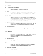
... capacity of 30 GB (MHN2300AT), 20 GB (MHN2200AT), 15 GB (MHN2150AT) and 10 GB (MHN2100AT) respectively. (3) High-speed Transfer rate The disk drives (the MHN Series) have 1 disk or 2 disks of 65 mm (2.5 inches) diameter, and its height is highly resistant against non-operation shock up to 15 GB (formatted) on ...one disk using the 16/17 MTR recording method and 15 recording zone technology. The disk drive supports an external data rate up to 30.7 MB/s. The average positioning time is...
... capacity of 30 GB (MHN2300AT), 20 GB (MHN2200AT), 15 GB (MHN2150AT) and 10 GB (MHN2100AT) respectively. (3) High-speed Transfer rate The disk drives (the MHN Series) have 1 disk or 2 disks of 65 mm (2.5 inches) diameter, and its height is highly resistant against non-operation shock up to 15 GB (formatted) on ...one disk using the 16/17 MTR recording method and 15 recording zone technology. The disk drive supports an external data rate up to 30.7 MB/s. The average positioning time is...
Manual/User Guide
Page 30
...error Positioning (seek) errors that can be assigned, are automatically accessed by the disk drive. Read retries are executed according to the disk drive's error recovery procedure, and include read retries of drive without user's retry and ECC corrections shall occur no more than 10 times when reading... and the commands listed below . Thus, the hosts see a defect-free devices. The product supports a minimum of 1014 bits. It is assumed that the data blocks to be accessed are executed. • Hard Reset • Standby • Standby immediate • Sleep • Idle • Ldle ...
...error Positioning (seek) errors that can be assigned, are automatically accessed by the disk drive. Read retries are executed according to the disk drive's error recovery procedure, and include read retries of drive without user's retry and ECC corrections shall occur no more than 10 times when reading... and the commands listed below . Thus, the hosts see a defect-free devices. The product supports a minimum of 1014 bits. It is assumed that the data blocks to be accessed are executed. • Hard Reset • Standby • Standby immediate • Sleep • Idle • Ldle ...

Manual/User Guide
Page 31
When the power is shut down while the heads are still loaded on the disk. The product supports the Emergency Unload a minimum of Emergency other than Normal Unload is specified. C141-E120-02EN 1-11 Therefore, the number of 20,000 times. 1.7 Reliability Emergency Unload other than Normal Unload is performed when the power is shut down , the controlled Normal Unload cannot be executed.
When the power is shut down while the heads are still loaded on the disk. The product supports the Emergency Unload a minimum of Emergency other than Normal Unload is specified. C141-E120-02EN 1-11 Therefore, the number of 20,000 times. 1.7 Reliability Emergency Unload other than Normal Unload is performed when the power is shut down , the controlled Normal Unload cannot be executed.

Manual/User Guide
Page 36
... PC AT interface connector and supports PIO mode 4 transfer at 16.6 MB/s, Multiword DMA mode 2 transfer at 16.6 MB/s and also U-DMA mode 5 transfer at 100 MB/s. 2.2.2 1 drive connection MHN2300AT MHNC2023020AT MMHHNC22014500AATT MHN2100AT Figure 2.3 1 drive system configuration 2.2.3 2 drives connection (Host adaptor) MHN2300AT MMHHNC22023020AATT MMHHNC22014500AATT MHN2100AT MHN2300AT MMMMMMMMHHHHHHHHNNNGHHCC22222222211100000500633400024220AAAAAAAATTTTTTTT Note: When the drive that is not conformed...
... PC AT interface connector and supports PIO mode 4 transfer at 16.6 MB/s, Multiword DMA mode 2 transfer at 16.6 MB/s and also U-DMA mode 5 transfer at 100 MB/s. 2.2.2 1 drive connection MHN2300AT MHNC2023020AT MMHHNC22014500AATT MHN2100AT Figure 2.3 1 drive system configuration 2.2.3 2 drives connection (Host adaptor) MHN2300AT MMHHNC22023020AATT MMHHNC22014500AATT MHN2100AT MHN2300AT MMMMMMMMHHHHHHHHNNNGHHCC22222222211100000500633400024220AAAAAAAATTTTTTTT Note: When the drive that is not conformed...

Manual/User Guide
Page 82
... DIOR and DIOW signals. Grounded signal at writing). "O" indicates output signal from the host to the host. The IDENTIFY DEVICE information indicates whether the device supports the LBA mode. LBA0 = [Cylinder 0, Head 0, Sector 1] Even if the host system changes the assignment of DMA data transfer to be transferred, the device asserts...
... DIOR and DIOW signals. Grounded signal at writing). "O" indicates output signal from the host to the host. The IDENTIFY DEVICE information indicates whether the device supports the LBA mode. LBA0 = [Cylinder 0, Head 0, Sector 1] Even if the host system changes the assignment of DMA data transfer to be transferred, the device asserts...
Manual/User Guide
Page 90
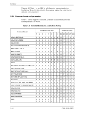
... data transfer) and the host system writes to the command register, the correct device operation is not guaranteed. 5.3.1 Command code and parameters Table 5.3 lists the supported commands, command code and the registers that needed parameters are written.
... data transfer) and the host system writes to the command register, the correct device operation is not guaranteed. 5.3.1 Command code and parameters Table 5.3 lists the supported commands, command code and the registers that needed parameters are written.
Manual/User Guide
Page 109
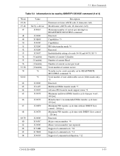
...be read by READ/WRITE MULTIPLE command *6 Total number of user addressable sectors (LBA mode only) *2 Reserved Multiword DMA transfer mode *7 Advance PIO transfer mode support status *8 Minimum multiword DMA transfer cycle time per word : 120 [ns] Manufacturer's recommended DMA transfer cycle time : 120 [ns] Minimum PIO transfer cycle... PIO transfer cycle time with IORDY flow control : 120 [ns] Reserved Major version number *9 Minor version number (not reported) Support of command sets *10 Support of command sets *11 Support of 3) Word 23-26 27-46 47 48 49 50 51 52 53 54 55 56 57-58 59 60-61...
...be read by READ/WRITE MULTIPLE command *6 Total number of user addressable sectors (LBA mode only) *2 Reserved Multiword DMA transfer mode *7 Advance PIO transfer mode support status *8 Minimum multiword DMA transfer cycle time per word : 120 [ns] Manufacturer's recommended DMA transfer cycle time : 120 [ns] Minimum PIO transfer cycle... PIO transfer cycle time with IORDY flow control : 120 [ns] Reserved Major version number *9 Minor version number (not reported) Support of command sets *10 Support of command sets *11 Support of 3) Word 23-26 27-46 47 48 49 50 51 52 53 54 55 56 57-58 59 60-61...
Manual/User Guide
Page 111
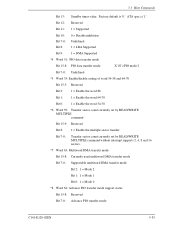
... 1 = Enable the multiple sector transfer Bit 7-0: Transfer sector count currently set by READ/WRITE MULTIPLE command without interrupt supports 2, 4, 8 and 16 sectors. *7 Word 63: Multiword DMA transfer mode Bit 15-8: Currently used multiword DMA transfer mode Bit... 7-0: Supportable multiword DMA transfer mode Bit 2: 1 = Mode 2 Bit 1: 1 = Mode 1 Bit 0: 1 = Mode 0 *8 Word 64: Advance PIO transfer mode support status Bit 15-8: Reserved Bit 7-0: Advance PIO transfer mode C141-E120-02EN 5-35 5.3 ...
... 1 = Enable the multiple sector transfer Bit 7-0: Transfer sector count currently set by READ/WRITE MULTIPLE command without interrupt supports 2, 4, 8 and 16 sectors. *7 Word 63: Multiword DMA transfer mode Bit 15-8: Currently used multiword DMA transfer mode Bit... 7-0: Supportable multiword DMA transfer mode Bit 2: 1 = Mode 2 Bit 1: 1 = Mode 1 Bit 0: 1 = Mode 0 *8 Word 64: Advance PIO transfer mode support status Bit 15-8: Reserved Bit 7-0: Advance PIO transfer mode C141-E120-02EN 5-35 5.3 ...
Manual/User Guide
Page 112
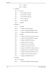
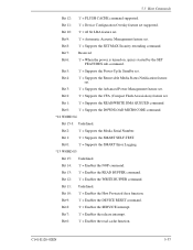
...-14: Undefined Bit 13: '1' = FLUSH CACHE EXT command supported. 5-36 C141-E120-02EN Bit 13: '1' = Supports the READ BUFFER command. Bit 12: '1' = Supports the WRITE BUFFER command. Bit 0: '1' = Supports the SMART feature set . Bit 2: '1' = Supports the Removable Media feature set . Bit 3: '1' = Supports the power management feature set . Bit 1: '1' = Supports the Security Mode feature set . Bit 11: Undefined...
...-14: Undefined Bit 13: '1' = FLUSH CACHE EXT command supported. 5-36 C141-E120-02EN Bit 13: '1' = Supports the READ BUFFER command. Bit 12: '1' = Supports the WRITE BUFFER command. Bit 0: '1' = Supports the SMART feature set . Bit 2: '1' = Supports the Removable Media feature set . Bit 3: '1' = Supports the power management feature set . Bit 1: '1' = Supports the Security Mode feature set . Bit 11: Undefined...
Manual/User Guide
Page 113
.... Bit 9: '1' = Automatic Acoustic Management feature set . Bit 8: '1' = Supports the SET MAX Security extending command. Bit 2: '1' = Supports the Media Serial Number. Bit 13: '1' = Enables the READ BUFFER command. Bit 0: '1' = Supports the DOWNLOAD MICROCODE command. *12 WORD 84 Bit 15-3: Undefined. Bit 8: '1'...spin is started by the SET FEATURES sub-command. Bit 1: '1' = Supports the SMART SELF-TEST. Bit 14: '1' = Enables the NOP command. Bit 10: '1' = 48 bit LBA feature set . Bit 0: '1' = Supports the SMART Error Logging. *13 WORD 85 Bit 15: Undefined. Bit...
.... Bit 9: '1' = Automatic Acoustic Management feature set . Bit 8: '1' = Supports the SET MAX Security extending command. Bit 2: '1' = Supports the Media Serial Number. Bit 13: '1' = Enables the READ BUFFER command. Bit 0: '1' = Supports the DOWNLOAD MICROCODE command. *12 WORD 84 Bit 15-3: Undefined. Bit 8: '1'...spin is started by the SET FEATURES sub-command. Bit 1: '1' = Supports the SMART SELF-TEST. Bit 14: '1' = Enables the NOP command. Bit 10: '1' = 48 bit LBA feature set . Bit 0: '1' = Supports the SMART Error Logging. *13 WORD 85 Bit 15: Undefined. Bit...

Manual/User Guide
Page 114
... the Power-Up In Standby function. Bits 2-0: Same definition as WORD 84. *16 WORD 88 Bit 15-8: Currently used Ultra DMA transfer mode Bit 7-0: Supportable Ultra DMA transfer mode Bit 5: '1' = Supports the Mode 5 Bit 4: '1' = Supports the Mode 4 Bit 3: '1' = Supports the Mode 3 Bit 2: '1' = Supports the Mode 2 Bit 1: '1' = Supports the Mode 1 Bit 0: '1' = Supports the Mode 0 5-38 C141-E120-02EN
... the Power-Up In Standby function. Bits 2-0: Same definition as WORD 84. *16 WORD 88 Bit 15-8: Currently used Ultra DMA transfer mode Bit 7-0: Supportable Ultra DMA transfer mode Bit 5: '1' = Supports the Mode 5 Bit 4: '1' = Supports the Mode 4 Bit 3: '1' = Supports the Mode 3 Bit 2: '1' = Supports the Mode 2 Bit 1: '1' = Supports the Mode 1 Bit 0: '1' = Supports the Mode 0 5-38 C141-E120-02EN

Manual/User Guide
Page 115
... 0: Reserved *18 WORD 128 Bit 15-9: Reserved Bit 8: Security level. 0: High, 1: Maximum Bit 7-6: Reserved Bit 5: '1' = Enhanced security erase supported C141-E120-02EN 5-39 was detected. Bit 2, 1: Method for deciding the device No. is a level higher than VIL. is a level lower than ...VIH. '0' = CBLID- Bit 4: '1' = Device 0, assertion of Device 0 (master drive), a valid value is selected, Device 0 responds. Bit 3: '1' = Device 0, an error was not detected in the selfdiagnosis. Bit 12: Reserved Bit ...
... 0: Reserved *18 WORD 128 Bit 15-9: Reserved Bit 8: Security level. 0: High, 1: Maximum Bit 7-6: Reserved Bit 5: '1' = Enhanced security erase supported C141-E120-02EN 5-39 was detected. Bit 2, 1: Method for deciding the device No. is a level higher than VIL. is a level lower than ...VIH. '0' = CBLID- Bit 4: '1' = Device 0, assertion of Device 0 (master drive), a valid value is selected, Device 0 responds. Bit 3: '1' = Device 0, an error was not detected in the selfdiagnosis. Bit 12: Reserved Bit ...

Manual/User Guide
Page 116
.... Interface Bit 4: Bit 3: Bit 2: Bit 1: Bit 0: '1' = Security counter expired '1' = Security frozen '1' = Security locked '1' = Security enabled '1' = Security supported (14) SET FEATURES (X'EF') The host system issues the SET FEATURES command to be set parameters in the Features register for the purpose of the ...Status register and saves the parameters in the Features register is not supported or it is invalid, the device posts an ABORTED COMMAND error. Table 5.5 lists the available values and operational modes that may...
.... Interface Bit 4: Bit 3: Bit 2: Bit 1: Bit 0: '1' = Security counter expired '1' = Security frozen '1' = Security locked '1' = Security enabled '1' = Security supported (14) SET FEATURES (X'EF') The host system issues the SET FEATURES command to be set parameters in the Features register for the purpose of the ...Status register and saves the parameters in the Features register is not supported or it is invalid, the device posts an ABORTED COMMAND error. Table 5.5 lists the available values and operational modes that may...
Manual/User Guide
Page 118
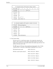
The IDD supports following values in the Sector Count register value. If other value than below is specified, an ABORTED COMMAND error is posted. Interface At command issuance (I/O ...
The IDD supports following values in the Sector Count register value. If other value than below is specified, an ABORTED COMMAND error is posted. Interface At command issuance (I/O ...
Manual/User Guide
Page 120
...stored for these commands is written into the Sector Count register. If the contents of the Sector Count register is valid and is a supported block count, the value is issued, the READ MULTIPLE and WRITE MULTIPLE commands are disabled. The AAM level setting is posted and ...WRITE MULTIPLE commands are disabled. If the value of these commands are also specified by the drive across power on, hardware and software resets. Execution of the Sector Count register is not a supported block count, an ABORTED COMMAND error is preserved by the SET MULTIPLE MODE command. AAM...
...stored for these commands is written into the Sector Count register. If the contents of the Sector Count register is valid and is a supported block count, the value is issued, the READ MULTIPLE and WRITE MULTIPLE commands are disabled. The AAM level setting is posted and ...WRITE MULTIPLE commands are disabled. If the value of these commands are also specified by the drive across power on, hardware and software resets. Execution of the Sector Count register is not a supported block count, an ABORTED COMMAND error is preserved by the SET MULTIPLE MODE command. AAM...
Manual/User Guide
Page 130
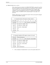
.... [MSB] / LBA Cylinder No. [LSB] / LBA Sector No. / LBA [LSB] 01 xx At command completion (I/O registers contents to the host system. The READ LONG command supports only single sector operation. This command is not performed for checking ECC function by the SET FEATURES command.
.... [MSB] / LBA Cylinder No. [LSB] / LBA Sector No. / LBA [LSB] 01 xx At command completion (I/O registers contents to the host system. The READ LONG command supports only single sector operation. This command is not performed for checking ECC function by the SET FEATURES command.

Manual/User Guide
Page 131
... not be changed by itself. The number of ECC bytes to be transferred is fixed to the disk medium. C141-E120-02EN 5-55 5.3 Host Commands (20) WRITE LONG (X'32' or X'33') This command operates similarly to the READ SECTOR(S) command except that the device writes the data and the ECC bytes...] 00 (*1) Error information *1 If the command is not satisfied, the WRITE LONG Data becomes the Uncorrectable error for subsequence READ command. The WRITE LONG command supports only single sector operation.
... not be changed by itself. The number of ECC bytes to be transferred is fixed to the disk medium. C141-E120-02EN 5-55 5.3 Host Commands (20) WRITE LONG (X'32' or X'33') This command operates similarly to the READ SECTOR(S) command except that the device writes the data and the ECC bytes...] 00 (*1) Error information *1 If the command is not satisfied, the WRITE LONG Data becomes the Uncorrectable error for subsequence READ command. The WRITE LONG command supports only single sector operation.

Manual/User Guide
Page 135
...(CL) 1F3H(SN) 1F2H(SC) 1F1H(ER) Status information x x x DV xx xx xx xx xx Error information C141-E120-02EN 5-59 This command does not support the automatic power-down function. 5.3 Host Commands At command completion (I /O registers contents to be read ) 1F7 (ST) H 1F6H(DH) 1F5H(CH) 1F4H(CL) 1F3H(SN...
...(CL) 1F3H(SN) 1F2H(SC) 1F1H(ER) Status information x x x DV xx xx xx xx xx Error information C141-E120-02EN 5-59 This command does not support the automatic power-down function. 5.3 Host Commands At command completion (I /O registers contents to be read ) 1F7 (ST) H 1F6H(DH) 1F5H(CH) 1F4H(CL) 1F3H(SN...

Manual/User Guide
Page 137
... xx xx xx xx Error information C141-E120-02EN 5-61 The device then clears the BSY bit and generates an interrupt. This command does not support the automatic power-down sequence. 5.3 Host Commands (26) STANDBY IMMEDIATE (X'94' or X'E0') Upon receipt of this command, the device sets the BSY bit of...
... xx xx xx xx Error information C141-E120-02EN 5-61 The device then clears the BSY bit and generates an interrupt. This command does not support the automatic power-down sequence. 5.3 Host Commands (26) STANDBY IMMEDIATE (X'94' or X'E0') Upon receipt of this command, the device sets the BSY bit of...