Manual/User Guide
Page 37
...(PIO mode 4 or DMA mode 2 U-DMA mode 5), occurrence of ringing or crosstalk of the disk drive. The disk drive is an abbreviation of the signal lines including the HA and cable does not exceed the ATA-5 standard, ...and the cable length between the HA and the disk drive may be contacted with the spindle motor. No need to the ATA-5 interface. C141-E120-02EN 2-5 Thus... could be a great cause of the obstruction of address decoder, driver, and receiver. 2.2 System Configuration IMPORTANT HA (host adaptor) consists of system reliability.
...(PIO mode 4 or DMA mode 2 U-DMA mode 5), occurrence of ringing or crosstalk of the disk drive. The disk drive is an abbreviation of the signal lines including the HA and cable does not exceed the ATA-5 standard, ...and the cable length between the HA and the disk drive may be contacted with the spindle motor. No need to the ATA-5 interface. C141-E120-02EN 2-5 Thus... could be a great cause of the obstruction of address decoder, driver, and receiver. 2.2 System Configuration IMPORTANT HA (host adaptor) consists of system reliability.

Manual/User Guide
Page 46
.... HDD is occasionally damaged by the impact of the driver. (2) Please observe the tightening torque of a low impact when you use the driver of the screw strictly. Recommended equipments ESD Shock Contents Wrist strap ESD mat Low shock driver Model JX-1200-3056-8 SKY-8A (Color Seiden Mat...3M Achilles HIOS 3-8 C141-E120-02EN Do not place HDD vertically to avoid falling down. Do not drop. Installation (1) Please use an electric driver. Do not hit HDD each other. Figure 3.7 Handling cautions - General notes Wrist strap Use the Wrist strap. ESD mat Shock absorbing mat ...
.... HDD is occasionally damaged by the impact of the driver. (2) Please observe the tightening torque of a low impact when you use the driver of the screw strictly. Recommended equipments ESD Shock Contents Wrist strap ESD mat Low shock driver Model JX-1200-3056-8 SKY-8A (Color Seiden Mat...3M Achilles HIOS 3-8 C141-E120-02EN Do not place HDD vertically to avoid falling down. Do not drop. Installation (1) Please use an electric driver. Do not hit HDD each other. Figure 3.7 Handling cautions - General notes Wrist strap Use the Wrist strap. ESD mat Shock absorbing mat ...

Manual/User Guide
Page 56
Theory of Device Operation 4.3 Circuit Configuration Figure 4.2 shows the power supply configuration of the disk drive, and Figure 4.3 shows the disk drive circuit configuration. (1) Read/write circuit The read/write circuit consists of the voice coil motor are listed below. • Data ...voice coil motor. read/write preamplifier (PreAMP) and read demodulation circuit using the servo information recorded on the media surface. (3) Spindle motor driver circuit The circuit measures the interval of a PHASE signal generated by a MPU and then reconverted to an analog signal for control of ...
Theory of Device Operation 4.3 Circuit Configuration Figure 4.2 shows the power supply configuration of the disk drive, and Figure 4.3 shows the disk drive circuit configuration. (1) Read/write circuit The read/write circuit consists of the voice coil motor are listed below. • Data ...voice coil motor. read/write preamplifier (PreAMP) and read demodulation circuit using the servo information recorded on the media surface. (3) Spindle motor driver circuit The circuit measures the interval of a PHASE signal generated by a MPU and then reconverted to an analog signal for control of ...
Manual/User Guide
Page 67
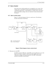
... capture MPU DSP unit Position Sense SVC (3) DAC (4) Power Amp VCM current (7) CSR VCM CSR: Current Sense Resister VCM: Voice Coil Motor (5) Spindle motor control (6) Driver Spindle motor Figure 4.7 Block diagram of servo control circuit (1) Microprocessor unit (MPU) The MPU includes the DSP unit, and the MPU starts the spindle motor...
... capture MPU DSP unit Position Sense SVC (3) DAC (4) Power Amp VCM current (7) CSR VCM CSR: Current Sense Resister VCM: Voice Coil Motor (5) Spindle motor control (6) Driver Spindle motor Figure 4.7 Block diagram of servo control circuit (1) Microprocessor unit (MPU) The MPU includes the DSP unit, and the MPU starts the spindle motor...
Manual/User Guide
Page 69
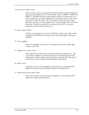
...the interrupt generated periodically, compares with A-B and C-D processed. (3) D/A converter (DAC) The D/A converter (DAC) converts the VCM drive current value (digital value) calculated by the DSP unit into analog values and transfers them to the power amplifier. (4) Power amplifier The...controls current at the power amplifier by converting the VCM current into the motor coil according to the differentiation (aberration). (6) Driver circuit The driver circuit is a power amplitude circuit that time the AGC circuit is recognized by Fourierdemodulator in the servo burst capture circuit....
...the interrupt generated periodically, compares with A-B and C-D processed. (3) D/A converter (DAC) The D/A converter (DAC) converts the VCM drive current value (digital value) calculated by the DSP unit into analog values and transfers them to the power amplifier. (4) Power amplifier The...controls current at the power amplifier by converting the VCM current into the motor coil according to the differentiation (aberration). (6) Driver circuit The driver circuit is a power amplitude circuit that time the AGC circuit is recognized by Fourierdemodulator in the servo burst capture circuit....
Manual/User Guide
Page 74
...filtering the position difference between the specified target position and the current position for each sampling time, the VCM drive current is digitally executed by the firmware. There are digitally controlled by the firmware. 4.7.5 Spindle motor control ..., the spindle motor is started in the following sequence: a) After the power is turned on the MPU manufactured by Fujitsu. b) When the charge pump capacitor is charged enough, the MPU sets the SVC to the disk. The charged amount...half-wave analog current control circuit is used as the spindle motor driver (called SVC hereafter).
...filtering the position difference between the specified target position and the current position for each sampling time, the VCM drive current is digitally executed by the firmware. There are digitally controlled by the firmware. 4.7.5 Spindle motor control ..., the spindle motor is started in the following sequence: a) After the power is turned on the MPU manufactured by Fujitsu. b) When the charge pump capacitor is charged enough, the MPU sets the SVC to the disk. The charged amount...half-wave analog current control circuit is used as the spindle motor driver (called SVC hereafter).

Manual/User Guide
Page 191
...0 150 0 150 0 150 0 100 0 100 0 75 Limited interlock time (*1) tMLI 20 20 20 20 20 20 Interlock time with a signal before driving IORDY (*4) tACK 20 20 20 20 20 20 Setup and hold (tDH, tCH) times in burst initiation and from STROBE edge to negation ...interlock time (*1) tAZ 10 10 10 10 10 10 Maximum time allowed for output drivers to release (from asserted or negated) tZAH 20 20 20 20 20 20 Minimum delay time required for output tZAD 0 0 0 0 0 0 Drivers to -recipient or recipientto-sender interlocks, i.e., one device at 1.5V. Note: ...
...0 150 0 150 0 150 0 100 0 100 0 75 Limited interlock time (*1) tMLI 20 20 20 20 20 20 Interlock time with a signal before driving IORDY (*4) tACK 20 20 20 20 20 20 Setup and hold (tDH, tCH) times in burst initiation and from STROBE edge to negation ...interlock time (*1) tAZ 10 10 10 10 10 10 Maximum time allowed for output drivers to release (from asserted or negated) tZAH 20 20 20 20 20 20 Minimum delay time required for output tZAD 0 0 0 0 0 0 Drivers to -recipient or recipientto-sender interlocks, i.e., one device at 1.5V. Note: ...
Manual/User Guide
Page 225
... DE is sealed to and output data from dust. C141-E120-02EN GL-1 If positions the read-write (R-W) head. BIOS standard for drives The BIOS standard collectively refers to the parameters defined by different vendors. A data block normally indicates a single sector. DE Disk enclosure. ... of these drives is daisychained with the ATA standard. The master is required. Interfaces based on the AT bus. Commands are called ATA interfaces. The actuator consists of these drives, a BIOS that can operate in the drive. To make full use of these drivers. The DE...
... DE is sealed to and output data from dust. C141-E120-02EN GL-1 If positions the read-write (R-W) head. BIOS standard for drives The BIOS standard collectively refers to the parameters defined by different vendors. A data block normally indicates a single sector. DE Disk enclosure. ... of these drives is daisychained with the ATA standard. The master is required. Interfaces based on the AT bus. Commands are called ATA interfaces. The actuator consists of these drives, a BIOS that can operate in the drive. To make full use of these drivers. The DE...


