

Manual/User Guide
Page 4
Figure 3.1 (1/1) Details - - signals are added. - Table 5.17 03 2000-12-13 - and DMACK- SET MAX commands are changed . - Table 1.1 - Specification (Number of Sections for DIOR-, DIOW- C141-E104-03EN Order No. Values of measurement have been corrected. *1 Section(s) with asterisk (*) refer to the previous edition ...
Figure 3.1 (1/1) Details - - signals are added. - Table 5.17 03 2000-12-13 - and DMACK- SET MAX commands are changed . - Table 1.1 - Specification (Number of Sections for DIOR-, DIOW- C141-E104-03EN Order No. Values of measurement have been corrected. *1 Section(s) with asterisk (*) refer to the previous edition ...
Manual/User Guide
Page 6
...terminology used in controller that the reader has a basic knowledge of hard disk drives and their features. C141-E104-03EN i Preface This manual describes the MHL Series and MHM Series, 2.5-inch hard disk drives. These drives have a built-in this manual: Overview of Manual CHAPTER 1 ...sections explaining the special terminology and abbreviations used in this manual. This manual describes the specifications and functions of the drives and explains in detail how to incorporate the drives into user systems. This manual assumes that is compatible with the ATA interface. CHAPTER 4...
...terminology used in controller that the reader has a basic knowledge of hard disk drives and their features. C141-E104-03EN i Preface This manual describes the MHL Series and MHM Series, 2.5-inch hard disk drives. These drives have a built-in this manual: Overview of Manual CHAPTER 1 ...sections explaining the special terminology and abbreviations used in this manual. This manual describes the specifications and functions of the drives and explains in detail how to incorporate the drives into user systems. This manual assumes that is compatible with the ATA interface. CHAPTER 4...
Manual/User Guide
Page 15
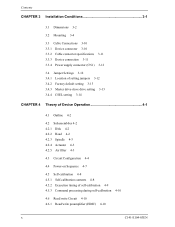
Contents CHAPTER 3 Installation Conditions 3-1 3.1 Dimensions 3-2 3.2 Mounting 3-4 3.3 Cable Connections 3-10 3.3.1 Device connector 3-10 3.3.2 Cable connector specifications 3-11 3.3.3 Device connection 3-11 3.3.4 Power supply connector (CN1) 3-12 3.4 Jumper Settings 3-12 3.4.1 Location of setting jumpers 3-12 3.4.2 Factory default setting 3-13 3.4.3 Master drive-slave drive setting 3-13 3.4.4 CSEL setting 3-14 CHAPTER 4 Theory of Device Operation 4-1 4.1 Outline 4-2 4.2 Subassemblies 4-2 4.2.1 Disk 4-2 4.2.2 Head 4-2 4.2.3 Spindle 4-3 4.2.4 Actuator...
Contents CHAPTER 3 Installation Conditions 3-1 3.1 Dimensions 3-2 3.2 Mounting 3-4 3.3 Cable Connections 3-10 3.3.1 Device connector 3-10 3.3.2 Cable connector specifications 3-11 3.3.3 Device connection 3-11 3.3.4 Power supply connector (CN1) 3-12 3.4 Jumper Settings 3-12 3.4.1 Location of setting jumpers 3-12 3.4.2 Factory default setting 3-13 3.4.3 Master drive-slave drive setting 3-13 3.4.4 CSEL setting 3-14 CHAPTER 4 Theory of Device Operation 4-1 4.1 Outline 4-2 4.2 Subassemblies 4-2 4.2.1 Disk 4-2 4.2.2 Head 4-2 4.2.3 Spindle 4-3 4.2.4 Actuator...

Manual/User Guide
Page 20
...generation of parallel CRC 5-105 Figure 5.9 Ultra DMA termination with pull-up or pull-down 5-106 Figure 5.10 Data transfer timing 5-108 Figure 5.11 Multiword DMA data transfer timing (mode 2) 5-109 Figure 5.12 ... Data buffer configuration 6-14 Table 1.1 Table 1.2 Table 1.3 Table 1.4 Table 1.5 Table 1.6 Specifications 1-4 Model names and product numbers 1-5 Current and power dissipation 1-6 Environmental specifications 1-7 Acoustic noise specification 1-8 Shock and vibration specification 1-8 Table 3.1 Surface temperature measurement points and standard values 3-7 Table 3.2 Cable connector...
...generation of parallel CRC 5-105 Figure 5.9 Ultra DMA termination with pull-up or pull-down 5-106 Figure 5.10 Data transfer timing 5-108 Figure 5.11 Multiword DMA data transfer timing (mode 2) 5-109 Figure 5.12 ... Data buffer configuration 6-14 Table 1.1 Table 1.2 Table 1.3 Table 1.4 Table 1.5 Table 1.6 Specifications 1-4 Model names and product numbers 1-5 Current and power dissipation 1-6 Environmental specifications 1-7 Acoustic noise specification 1-8 Shock and vibration specification 1-8 Table 3.1 Surface temperature measurement points and standard values 3-7 Table 3.2 Cable connector...
Manual/User Guide
Page 22
The MHL Series and MHM Series are 2.5-inch hard disk drives with built-in this chapter, and specifications and power requirement are described. CHAPTER 1 Device Overview 1.1 Features 1.2 Device Specifications 1.3 Power Requirements 1.4 Environmental Specifications 1.5 Acoustic Noise 1.6 Shock and Vibration 1.7 Reliability 1.8 Error Rate 1.9 Media Defects Overview and features are described in disk controllers. C141-E104-03EN 1-1 These disk drives use the AT-bus hard disk interface protocol and are compact and reliable.
The MHL Series and MHM Series are 2.5-inch hard disk drives with built-in this chapter, and specifications and power requirement are described. CHAPTER 1 Device Overview 1.1 Features 1.2 Device Specifications 1.3 Power Requirements 1.4 Environmental Specifications 1.5 Acoustic Noise 1.6 Shock and Vibration 1.7 Reliability 1.8 Error Rate 1.9 Media Defects Overview and features are described in disk controllers. C141-E104-03EN 1-1 These disk drives use the AT-bus hard disk interface protocol and are compact and reliable.
Manual/User Guide
Page 25
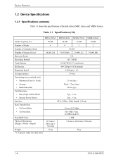
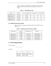
...;70.0 mm Weight 134 g 98 g *1: Capacity under the LBA mode. 1-4 C141-E104-03EN Table 1.1 Specifications (1/2) MHL2300AT MHM2200AT MHM2150AT MHM2100AT Format Capacity (*1) 30 GB 20 GB 15 GB 10 GB Number of Heads 6 4 3 2 Number of Cylinders (User) 19,904 Number of the disk drives (MHL Series and MHM Series). Cable length: 0.46 m) Data Transfer Rate • To/From Media...
...;70.0 mm Weight 134 g 98 g *1: Capacity under the LBA mode. 1-4 C141-E104-03EN Table 1.1 Specifications (1/2) MHL2300AT MHM2200AT MHM2150AT MHM2100AT Format Capacity (*1) 30 GB 20 GB 15 GB 10 GB Number of Heads 6 4 3 2 Number of Cylinders (User) 19,904 Number of the disk drives (MHL Series and MHM Series). Cable length: 0.46 m) Data Transfer Rate • To/From Media...
Manual/User Guide
Page 26
... Table 1.2 lists the model names and product numbers of sectors are as follows. Table 1.1 Specifications (2/2) Capacity 8.45 GB 8.45 GB 8.45 GB 8.45 GB No. Table 1.2 Model names and product numbers Model Name MHL2300AT MHM2200AT MHM2150AT MHM2100AT Capacity (user area) 30 GB 20 GB 15 GB 10 GB Mounting screw M3, depth 3 M3, depth 3 M3, depth 3 M3, depth 3 Order No. CA05428...
... Table 1.2 lists the model names and product numbers of sectors are as follows. Table 1.1 Specifications (2/2) Capacity 8.45 GB 8.45 GB 8.45 GB 8.45 GB No. Table 1.2 Model names and product numbers Model Name MHL2300AT MHM2200AT MHM2150AT MHM2100AT Capacity (user area) 30 GB 20 GB 15 GB 10 GB Mounting screw M3, depth 3 M3, depth 3 M3, depth 3 M3, depth 3 Order No. CA05428...

Manual/User Guide
Page 28
...) monitor +5 V. These prevent data from being destroyed and eliminates the need to 12,000 m C141-E104-03EN 1-7 Table 1.4 Environmental specifications Item Temperature • Operating • Non-operating • Thermal Gradient Humidity • Operating • Non-operating • Maximum Wet... Bulb Altitude (relative to sea level) • Operating • Non-operating Specification 5°C to 55°C (ambient) 5°C to 60°C (disk enclosure surface) -40°C to 65°C 20°C/h or...
...) monitor +5 V. These prevent data from being destroyed and eliminates the need to 12,000 m C141-E104-03EN 1-7 Table 1.4 Environmental specifications Item Temperature • Operating • Non-operating • Thermal Gradient Humidity • Operating • Non-operating • Maximum Wet... Bulb Altitude (relative to sea level) • Operating • Non-operating Specification 5°C to 55°C (ambient) 5°C to 60°C (disk enclosure surface) -40°C to 65°C 20°C/h or...

Manual/User Guide
Page 29
... Vibration (swept sine, one octave per minute) • Operating • Non-operating Shock (half-sine pulse) • Operating • Non-operating Specification 5 to 500 Hz, 1.0G 0-peak (MHL series) 5 to 400 Hz, 1.0G 0-peak (MHM series) (without non-recovered errors) (9.8 m/s2 ... series 120G 0-peak (1,176 m/s2 0-peak) 11 ms duration (no damage) 1-8 C141-E104-03EN Table 1.5 Acoustic noise specification Item Sound Pressure • Idle mode (DRIVE READY) Specification 30 dBA typical at 1 m Note: Measure the noise from the cover top surface. 1.6 Shock and Vibration Table 1.6 lists...
... Vibration (swept sine, one octave per minute) • Operating • Non-operating Shock (half-sine pulse) • Operating • Non-operating Specification 5 to 500 Hz, 1.0G 0-peak (MHL series) 5 to 400 Hz, 1.0G 0-peak (MHM series) (without non-recovered errors) (9.8 m/s2 ... series 120G 0-peak (1,176 m/s2 0-peak) 11 ms duration (no damage) 1-8 C141-E104-03EN Table 1.5 Acoustic noise specification Item Sound Pressure • Idle mode (DRIVE READY) Specification 30 dBA typical at 1 m Note: Measure the noise from the cover top surface. 1.6 Shock and Vibration Table 1.6 lists...
Manual/User Guide
Page 34
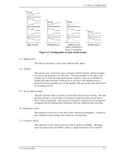
... the spindle motor is stopped, the head assembly stays in the specific CSS zone on the blower effect of disk media heads (3) Spindle motor The disks are rotated by the read by a direct drive Hall-less DC motor. (4) Actuator The actuator uses a revolving ... C141-E104-03EN 2-3 2.1 Device Configuration Head 5 4 3 2 1 0 Head 3 2 1 0 Head 3 2 1 0 Head 1 0 MHL2300AT MHM2200AT MHM2150AT (Either of head 0 or MHM2100AT head 3 is mounted.) Figure 2.2 Configuration of the rotating disk. The disk enclosure features a closed loop air circulation system that relies on the disk and is...
... the spindle motor is stopped, the head assembly stays in the specific CSS zone on the blower effect of disk media heads (3) Spindle motor The disks are rotated by the read by a direct drive Hall-less DC motor. (4) Actuator The actuator uses a revolving ... C141-E104-03EN 2-3 2.1 Device Configuration Head 5 4 3 2 1 0 Head 3 2 1 0 Head 3 2 1 0 Head 1 0 MHL2300AT MHM2200AT MHM2150AT (Either of head 0 or MHM2100AT head 3 is mounted.) Figure 2.2 Configuration of the rotating disk. The disk enclosure features a closed loop air circulation system that relies on the disk and is...

Manual/User Guide
Page 42
... Screw Details of mounting Do not use the center hole. IMPORTANT Use M3 screw for the mounting screw and the screw length should satisfy the specification in Figure 3.3.
... Screw Details of mounting Do not use the center hole. IMPORTANT Use M3 screw for the mounting screw and the screw length should satisfy the specification in Figure 3.3.

Manual/User Guide
Page 48
Figure 3.9 Cable connections C141-E104-03EN 3-11 3.3 Cable Connections 3.3.2 Cable connector specifications Table 3.2 lists the recommended specifications for cables carrying differential signals. 3.3.3 Device connection Figure 3.9 shows how to connect the devices. A twisted cable or a cable... with wires that have become separated from the ribbon may cause crosstalk between signal lines. Table 3.2 Cable connector specifications ATA interface and power supply cable (44-pin type) Name Cable socket (44-pin type) Model 89361-144 Manufacturer BERG IMPORTANT For ...
Figure 3.9 Cable connections C141-E104-03EN 3-11 3.3 Cable Connections 3.3.2 Cable connector specifications Table 3.2 lists the recommended specifications for cables carrying differential signals. 3.3.3 Device connection Figure 3.9 shows how to connect the devices. A twisted cable or a cable... with wires that have become separated from the ribbon may cause crosstalk between signal lines. Table 3.2 Cable connector specifications ATA interface and power supply cable (44-pin type) Name Cable socket (44-pin type) Model 89361-144 Manufacturer BERG IMPORTANT For ...

Manual/User Guide
Page 76
... signal. This makes the flowed current into the motor higher and the rotational speed up. C141-E104-03EN 4-23 When a PHASE signal is waiting for a specific period, the MPU resets the SVC and starts from the SVC, and waits till the rotational speed reaches 4,200 rpm. When the rotational speed reaches...
... signal. This makes the flowed current into the motor higher and the rotational speed up. C141-E104-03EN 4-23 When a PHASE signal is waiting for a specific period, the MPU resets the SVC and starts from the SVC, and waits till the rotational speed reaches 4,200 rpm. When the rotational speed reaches...

Manual/User Guide
Page 86
... be transferred to the error. Under the LBA mode, this register is X'00', the sector count is posted. (3) Features register (X'1F1') The Features register provides specific feature to 0. When the value in a read or write operation between X'01' and [the number of sectors to be between the host system and the...
... be transferred to the error. Under the LBA mode, this register is X'00', the sector count is posted. (3) Features register (X'1F1') The Features register provides specific feature to 0. When the value in a read or write operation between X'01' and [the number of sectors to be between the host system and the...

Manual/User Guide
Page 107
... interrupt. When the SC register is specified to X'00', an ABORTED COMMAND error is specified, this command. In LBA mode The device ignores the L bit specification and operates with this command terminates normally. An accessible area of this command within a default area. It is recommended that the host system refers the... system can set by the IDENTIFY DEVICE command. 5-30 C141-E104-03EN The parameters set the number of sectors per cylinder with the CHS mode specification.
... interrupt. When the SC register is specified to X'00', an ABORTED COMMAND error is specified, this command. In LBA mode The device ignores the L bit specification and operates with this command terminates normally. An accessible area of this command within a default area. It is recommended that the host system refers the... system can set by the IDENTIFY DEVICE command. 5-30 C141-E104-03EN The parameters set the number of sectors per cylinder with the CHS mode specification.

Manual/User Guide
Page 143
... with insurance failure threshold values. The host can predict failures in the enabled (when the SC register specification ≠ 00h) or disabled (when the SC register specification = 00) state. This setting is preserved whether the drive's power is nearing the end of 3) Features Resister X'DA' X'DB' Function SMART Return Status: When the device...
... with insurance failure threshold values. The host can predict failures in the enabled (when the SC register specification ≠ 00h) or disabled (when the SC register specification = 00) state. This setting is preserved whether the drive's power is nearing the end of 3) Features Resister X'DA' X'DB' Function SMART Return Status: When the device...
Manual/User Guide
Page 157
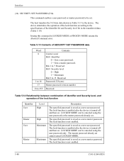
... password already set . The lock function is not enabled. Interface (34) SECURITY SET PASSWORD (F1h) This command enables a user password or master password to the specifications of the Identifier bit and Security level bit in the transferred data. (Table 5.14) Issuing this command in Table 5.13 to 15 Reserved Password (32...
... password already set . The lock function is not enabled. Interface (34) SECURITY SET PASSWORD (F1h) This command enables a user password or master password to the specifications of the Identifier bit and Security level bit in the transferred data. (Table 5.14) Issuing this command in Table 5.13 to 15 Reserved Password (32...

Manual/User Guide
Page 170
... phase, and the Ultra DMA burst termination phase. f) Ultra DMA data out burst The device should not invert the state of these phases, 5.6.4 defines the specific timing requirements). If the two values do not match the device reports an error in burst The device starts transmission of the command. If an...
... phase, and the Ultra DMA burst termination phase. f) Ultra DMA data out burst The device should not invert the state of these phases, 5.6.4 defines the specific timing requirements). If the two values do not match the device reports an error in burst The device starts transmission of the command. If an...

Manual/User Guide
Page 172
...:0) within tENV after negating DMACK- within tAZ after asserting DMACK-. 8) The device may occur in the order they are listed unless otherwise specifically allowed (see 5.6.4.1 and 5.6.4.2 for the remaining Ultra DMA burst to be performed. However, the assertion of the STROBE signal should return ...the STROBE signal to its asserted state should not be changed for specific timing requirements): 1) The host shall keep DMACK- h) Once the receiving side has outputted the ending request, the negated state of ...
...:0) within tENV after negating DMACK- within tAZ after asserting DMACK-. 8) The device may occur in the order they are listed unless otherwise specifically allowed (see 5.6.4.1 and 5.6.4.2 for the remaining Ultra DMA burst to be performed. However, the assertion of the STROBE signal should return ...the STROBE signal to its asserted state should not be changed for specific timing requirements): 1) The host shall keep DMACK- h) Once the receiving side has outputted the ending request, the negated state of ...

Manual/User Guide
Page 173
... than tDVS after changing the state of data onto DD (15:0). 5.5.3.2 The data in transfer The following steps shall occur in step (10). 12) To transfer the first word of data the device shall negate DSTROBE within tFS after the host has asserted DMACK-, negated STOP,... DMA burst termination, the host shall negate HDMARDY- This step may occur when the device first drives DD (15:0) in the order they are listed unless otherwise specifically allowed (see 5.6.4.3 and 5.6.4.2): 1) The device shall drive a data word onto DD (15:0). 2) The device shall generate a DSTROBE edge to latch ...
... than tDVS after changing the state of data onto DD (15:0). 5.5.3.2 The data in transfer The following steps shall occur in step (10). 12) To transfer the first word of data the device shall negate DSTROBE within tFS after the host has asserted DMACK-, negated STOP,... DMA burst termination, the host shall negate HDMARDY- This step may occur when the device first drives DD (15:0) in the order they are listed unless otherwise specifically allowed (see 5.6.4.3 and 5.6.4.2): 1) The device shall drive a data word onto DD (15:0). 2) The device shall generate a DSTROBE edge to latch ...
