
Manual/User Guide
Page 18
Glossary 6.1.1 Response to power-on 6-2 6.1.2 Response to hardware reset 6-4 6.1.3 Response to software reset 6-5 6.1.4 Response to diagnostic command 6-6 6.2 Address Translation 6-7 6.2.1 Default parameters 6-7 6.2.2 Logical address 6-8 6.3 Power Save 6-9 6.3.1 Power save mode 6-9 6.3.2 Power commands 6-11 6.4 Defect Management 6-11 6.4.1 Spare area 6-12 6.4.2 ...
Glossary 6.1.1 Response to power-on 6-2 6.1.2 Response to hardware reset 6-4 6.1.3 Response to software reset 6-5 6.1.4 Response to diagnostic command 6-6 6.2 Address Translation 6-7 6.2.1 Default parameters 6-7 6.2.2 Logical address 6-8 6.3 Power Save 6-9 6.3.1 Power save mode 6-9 6.3.2 Power commands 6-11 6.4 Defect Management 6-11 6.4.1 Spare area 6-12 6.4.2 ...

Manual/User Guide
Page 20
...Figure 5.8 An example of generation of parallel CRC 5-105 Figure 5.9 Ultra DMA termination with pull-up or pull-down 5-106 Figure 5.10 Data transfer timing 5-108 Figure 5.11 Multiword DMA data transfer timing (mode 2) 5-109 Figure 5.12 Starting of Ultra DMA data In...out burst 5-121 Figure 5.22 Power on Reset Timing 5-122 Figure 6.1 Response to power-on 6-3 Figure 6.2 Response to hardware reset 6-4 Figure 6.3 Response to software reset 6-5 Figure 6.4 Response to diagnostic command 6-6 Figure 6.5 Address translation (example in CHS mode) 6-8 Figure 6.6 Address translation (example in LBA mode) 6-9...
...Figure 5.8 An example of generation of parallel CRC 5-105 Figure 5.9 Ultra DMA termination with pull-up or pull-down 5-106 Figure 5.10 Data transfer timing 5-108 Figure 5.11 Multiword DMA data transfer timing (mode 2) 5-109 Figure 5.12 Starting of Ultra DMA data In...out burst 5-121 Figure 5.22 Power on Reset Timing 5-122 Figure 6.1 Response to power-on 6-3 Figure 6.2 Response to hardware reset 6-4 Figure 6.3 Response to software reset 6-5 Figure 6.4 Response to diagnostic command 6-6 Figure 6.5 Address translation (example in CHS mode) 6-8 Figure 6.6 Address translation (example in LBA mode) 6-9...

Manual/User Guide
Page 90
... Bit 5 Bit 4 Bit 3 Bit 2 Bit 1 Bit 0 BSY DRDY DF DSC DRQ 0 0 ERR (2) Device Control register (X'3F6') The Device Control register contains device interrupt and software reset. Bit 1: nIEN bit enables an interrupt (INTRQ signal) from the Status register is not reset. Bit 7 Bit 6 Bit 5 Bit 4 Bit 3 Bit 2 Bit 1 Bit ...on the interface, setting this register does not imply Interrupt Acknowledge and INTRQ signal is that a read of hardware or software reset. C141-E104-03EN 5-13 The only difference from the device to the device by writing necessary parameters in related registers...
... Bit 5 Bit 4 Bit 3 Bit 2 Bit 1 Bit 0 BSY DRDY DF DSC DRQ 0 0 ERR (2) Device Control register (X'3F6') The Device Control register contains device interrupt and software reset. Bit 1: nIEN bit enables an interrupt (INTRQ signal) from the Status register is not reset. Bit 7 Bit 6 Bit 5 Bit 4 Bit 3 Bit 2 Bit 1 Bit ...on the interface, setting this register does not imply Interrupt Acknowledge and INTRQ signal is that a read of hardware or software reset. C141-E104-03EN 5-13 The only difference from the device to the device by writing necessary parameters in related registers...

Manual/User Guide
Page 118
... to power-on default settings after software reset. Transfer mode depends on , to remain the same even after software reset. Disables the write cache function. Enables the reverting to power-on or after software reset. Enables the read cache function.... Specifies the transfer of the Sector Count register. (Details are given later.) Enables the advanced power management function. 5.3 Host Commands Table 5.5 Features register values and settable modes Features Register X'02' X'03' X'05' X'55' X'66' X'82' X'85' X'AA' X'BB' X'CC' Drive...
... to power-on default settings after software reset. Transfer mode depends on , to remain the same even after software reset. Disables the write cache function. Enables the reverting to power-on or after software reset. Enables the read cache function.... Specifies the transfer of the Sector Count register. (Details are given later.) Enables the advanced power management function. 5.3 Host Commands Table 5.5 Features register values and settable modes Features Register X'02' X'03' X'05' X'55' X'66' X'82' X'85' X'AA' X'BB' X'CC' Drive...
Manual/User Guide
Page 121
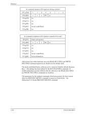
...) Status information x x x DV xx xx xx xx Sector count/block Error information After power-on or after the software is the READ MULTIPLE and WRITE MULTIPLE commands are disabled. The mode established before software reset is retained if disable default (Features Reg. = 66h setting) has been defined by the SET FEATURES command...
...) Status information x x x DV xx xx xx xx Sector count/block Error information After power-on or after the software is the READ MULTIPLE and WRITE MULTIPLE commands are disabled. The mode established before software reset is retained if disable default (Features Reg. = 66h setting) has been defined by the SET FEATURES command...

Manual/User Guide
Page 138
... completion (I /O register outputs are in high-impedance state. In the sleep mode, the spindle motor is stopped and the ATA interface section is to execute a software or hardware reset. The only way to release the device from sleep mode is inactive.
... completion (I /O register outputs are in high-impedance state. In the sleep mode, the spindle motor is stopped and the ATA interface section is to execute a software or hardware reset. The only way to release the device from sleep mode is inactive.
Manual/User Guide
Page 169
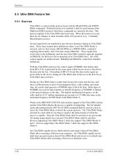
...Ultra DMA Mode 2 shall also support Ultra DMA Modes 0 and 1. An Ultra DMA capable device shall retain its default nonUltra DMA Modes after executing a Software reset sequence. All of DD (15:0) and this protocol is selected, and 2) a host issues a READ DMA or a WRITE DMA, command requiring... data transfer, and 3) the host asserts DMACK-. retain their standard definitions. With the Ultra DMA protocol, the control signal (STROBE) that drives the data onto the bus. An Ultra DMA capable device shall clear any given time. Interface 5.5 Ultra DMA Feature Set 5.5.1 Overview Ultra DMA...
...Ultra DMA Mode 2 shall also support Ultra DMA Modes 0 and 1. An Ultra DMA capable device shall retain its default nonUltra DMA Modes after executing a Software reset sequence. All of DD (15:0) and this protocol is selected, and 2) a host issues a READ DMA or a WRITE DMA, command requiring... data transfer, and 3) the host asserts DMACK-. retain their standard definitions. With the Ultra DMA protocol, the control signal (STROBE) that drives the data onto the bus. An Ultra DMA capable device shall clear any given time. Interface 5.5 Ultra DMA Feature Set 5.5.1 Overview Ultra DMA...

Manual/User Guide
Page 199
Interface 5.6.4 Power-on and reset Figure 5.22 shows power-on and reset (hardware and software reset) timing. (1) Only master device is present Power-on Reset Timing C141-E104-03EN negation 31 Figure 5.22 Power on Reset RESET- (2) Master and slave devices are present (2-drives configuration) 5-122 PDIAG-
Interface 5.6.4 Power-on and reset Figure 5.22 shows power-on and reset (hardware and software reset) timing. (1) Only master device is present Power-on Reset Timing C141-E104-03EN negation 31 Figure 5.22 Power on Reset RESET- (2) Master and slave devices are present (2-drives configuration) 5-122 PDIAG-

Manual/User Guide
Page 204
..., the slave device shall report its presence and the result of the self-diagnostics to software reset C141-E104-03EN 6-5 signal, and negates the DASP- X'3F6' Reg. Figure 6.3 Response to the master device as described below: PDIAG- If a slave device is ... checks the PDIAG- signal when negating the PDIAG- BSY bit X"00" Max. 31 sec. signal. Slave device BSY bit PDIAGDASP- signal for a software reset. signal for up to software reset The master device does not check the DASP- If the slave device is checked for up to 15 seconds to a slave device...
..., the slave device shall report its presence and the result of the self-diagnostics to software reset C141-E104-03EN 6-5 signal, and negates the DASP- X'3F6' Reg. Figure 6.3 Response to the master device as described below: PDIAG- If a slave device is ... checks the PDIAG- signal when negating the PDIAG- BSY bit X"00" Max. 31 sec. signal. Slave device BSY bit PDIAGDASP- signal for a software reset. signal for up to software reset The master device does not check the DASP- If the slave device is checked for up to 15 seconds to a slave device...

Manual/User Guide
Page 210
...standby mode from the standby mode is to execute a software or hardware reset. C141-E104-03EN 6-11 All the user space area are formatted at the factory shipment. Issued commands are invalid (ignored) in this mode. The drive enters the sleep mode under the following commands are ... following commands is issued, the command is executed normally and the device is still stayed in the standby mode. • Reset (hardware or software) • STANDBY command • STANDBY IMMEDIATE command • INITIALIZE DEVICE PARAMETERS command • CHECK POWER MODE command (4) Sleep mode The power...
...standby mode from the standby mode is to execute a software or hardware reset. C141-E104-03EN 6-11 All the user space area are formatted at the factory shipment. Issued commands are invalid (ignored) in this mode. The drive enters the sleep mode under the following commands are ... following commands is issued, the command is executed normally and the device is still stayed in the standby mode. • Reset (hardware or software) • STANDBY command • STANDBY IMMEDIATE command • INITIALIZE DEVICE PARAMETERS command • CHECK POWER MODE command (4) Sleep mode The power...