

Manual/User Guide
Page 20
...5.8 An example of generation of parallel CRC 5-93 Figure 5.9 Ultra DMA termination with pull-up or pull-down 5-94 Figure 5.10 Data transfer timing 5-96 Figure 5.11 Single word DMA data transfer timing (mode 2) 5-97 Figure 5.12 Multiword DMA data transfer... cylinder assignment 6-13 Figure 6.9 Data buffer configuration 6-14 Table 1.1 Table 1.2 Table 1.3 Table 1.4 Table 1.5 Table 1.6 Specifications 1-4 Model names and product numbers 1-5 Current and power dissipation 1-6 Environmental specifications 1-7 Acoustic noise specification 1-8 Shock and vibration specification 1-8 C141-E070-02EN xv
...5.8 An example of generation of parallel CRC 5-93 Figure 5.9 Ultra DMA termination with pull-up or pull-down 5-94 Figure 5.10 Data transfer timing 5-96 Figure 5.11 Single word DMA data transfer timing (mode 2) 5-97 Figure 5.12 Multiword DMA data transfer... cylinder assignment 6-13 Figure 6.9 Data buffer configuration 6-14 Table 1.1 Table 1.2 Table 1.3 Table 1.4 Table 1.5 Table 1.6 Specifications 1-4 Model names and product numbers 1-5 Current and power dissipation 1-6 Environmental specifications 1-7 Acoustic noise specification 1-8 Shock and vibration specification 1-8 C141-E070-02EN xv
Manual/User Guide
Page 26
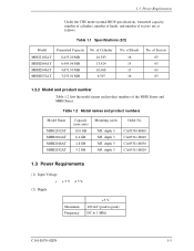
of the MHG Series and MHH Series. Table 1.2 Model names and product numbers Model Name MHG2102AT MHH2064AT MHH2048AT MHH2032AT Capacity (user area) 10.0 GB 6.4 GB 4.8 GB 3.2 GB Mounting screw Order No. of Sectors 63 63 63 63 1.2.2 Model and product number Table 1.2 lists the model names and product numbers of Cylinder 16,383 13,424 10,068 6,307 No. M3, depth 3 M3...
of the MHG Series and MHH Series. Table 1.2 Model names and product numbers Model Name MHG2102AT MHH2064AT MHH2048AT MHH2032AT Capacity (user area) 10.0 GB 6.4 GB 4.8 GB 3.2 GB Mounting screw Order No. of Sectors 63 63 63 63 1.2.2 Model and product number Table 1.2 lists the model names and product numbers of Cylinder 16,383 13,424 10,068 6,307 No. M3, depth 3 M3...
Manual/User Guide
Page 33
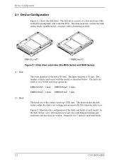
... and heads of disks used varies with the model, as described below. The head touches the disk surface while the disk is 65 mm. Numerals 0 to 5 indicate read /write and user data are written. The disk drive consists of the contact start /stop (CSS) type. MHG2102AT: 3 disks MHH2064AT: 2 disks MHH2048AT: 2 disks MHH2032AT: 1 disk...
... and heads of disks used varies with the model, as described below. The head touches the disk surface while the disk is 65 mm. Numerals 0 to 5 indicate read /write and user data are written. The disk drive consists of the contact start /stop (CSS) type. MHG2102AT: 3 disks MHH2064AT: 2 disks MHH2048AT: 2 disks MHH2032AT: 1 disk...

Manual/User Guide
Page 47
... differential signals. 3.3.3 Device connection Figure 3.8 shows how to connect the devices. Figure 3.8 Cable connections 3-10 C141-E070-02EN Table 3.2 Cable connector specifications ATA interface and power supply cable (44-pin type) Name Cable socket (44-pin type) Model 89361-144 Manufacturer BERG For the host interface cable, use a ribbon cable. This is...
... differential signals. 3.3.3 Device connection Figure 3.8 shows how to connect the devices. Figure 3.8 Cable connections 3-10 C141-E070-02EN Table 3.2 Cable connector specifications ATA interface and power supply cable (44-pin type) Name Cable socket (44-pin type) Model 89361-144 Manufacturer BERG For the host interface cable, use a ribbon cable. This is...

Manual/User Guide
Page 106
...Minimum multiword DMA transfer cycle time per track Total number of current sectors Transfer sector count currently set by IDENTIFY DEVICE command (2 of command sets *10 C141-E070-01EN 5-33 Set by a device X'8010' X'0000' X'0B00' X'0000' X'0200' X'0000' X'0007' (Variable) (Variable... X'0003' X'0078' X'0078' X'00F0' X'0078' X'0000' X'001E' X'0000' X'346B' Description Firmware revision (ASCII code, 8 characters, left) Model name (ASCII code, 40 characters, left) Maximum number of sectors per interrupt on READ/WRITE MULTIPLE command Reserved Capabilities *3 Reserved PIO data transfer mode *4 ...
...Minimum multiword DMA transfer cycle time per track Total number of current sectors Transfer sector count currently set by IDENTIFY DEVICE command (2 of command sets *10 C141-E070-01EN 5-33 Set by a device X'8010' X'0000' X'0B00' X'0000' X'0200' X'0000' X'0007' (Variable) (Variable... X'0003' X'0078' X'0078' X'00F0' X'0078' X'0000' X'001E' X'0000' X'346B' Description Firmware revision (ASCII code, 8 characters, left) Model name (ASCII code, 40 characters, left) Maximum number of sectors per interrupt on READ/WRITE MULTIPLE command Reserved Capabilities *3 Reserved PIO data transfer mode *4 ...

Manual/User Guide
Page 218
M Master 1-3 Master drive setting 3-10 Master password 5-68 Mean time between failures 1-8 Mean time to repair 1-8 Media defect 1-9 Microprocessor unit 4-14 Mis-hit 6-16 Model and product number 1-5 Model name and product number 1-5 Mounting 3-3 Move head to reference cylinder 4-15 MPU 4-14 MTBF 1-8 MTTR 1-8 Multiword DMA data transfer 5-80 Multiword DMA data transfer timing 5-...
M Master 1-3 Master drive setting 3-10 Master password 5-68 Mean time between failures 1-8 Mean time to repair 1-8 Media defect 1-9 Microprocessor unit 4-14 Mis-hit 6-16 Model and product number 1-5 Model name and product number 1-5 Mounting 3-3 Move head to reference cylinder 4-15 MPU 4-14 MTBF 1-8 MTTR 1-8 Multiword DMA data transfer 5-80 Multiword DMA data transfer timing 5-...

