
English manual
Page 1
P35A Series Motherboard User's Manual
P35A Series Motherboard User's Manual

English manual
Page 2
...visit Foxconn's website: http://www.foxconnchannel.com © All rights reserved. WEEE: The use motherboard better, and tells you purchased this product may not be caused by inappropriate waste handling of this manual may exist. Version: User's Manual V1.2 for P35A Series motherboard. ... are for reference only, please refer to the physical motherboard for specific features. Trademark: All trademarks are the property of their respective owners. By ensuring this product is the intellectual property of Foxconn, Inc. CAUTION Statement: This manual is disposed of correctly...
...visit Foxconn's website: http://www.foxconnchannel.com © All rights reserved. WEEE: The use motherboard better, and tells you purchased this product may not be caused by inappropriate waste handling of this manual may exist. Version: User's Manual V1.2 for P35A Series motherboard. ... are for reference only, please refer to the physical motherboard for specific features. Trademark: All trademarks are the property of their respective owners. By ensuring this product is the intellectual property of Foxconn, Inc. CAUTION Statement: This manual is disposed of correctly...
English manual
Page 3
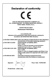
... information technology equipment ■ EN 61000-3-2/:2000 Electromagnetic compatibility (EMC) Part 3: Limits Section 2: Limits for harmonic current emissions (equipment input current declares that the product Motherboard P35A/P35A-S is in conformity with (reference to the specification under which conformity is declared in accordance with 89/336 EEC-EMC Directive) ■ EN 55022:1998...
... information technology equipment ■ EN 61000-3-2/:2000 Electromagnetic compatibility (EMC) Part 3: Limits Section 2: Limits for harmonic current emissions (equipment input current declares that the product Motherboard P35A/P35A-S is in conformity with (reference to the specification under which conformity is declared in accordance with 89/336 EEC-EMC Directive) ■ EN 55022:1998...
English manual
Page 4
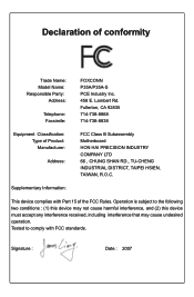
...714-738-8868 714-738-8838 Equipment Classification: Type of conformity Trade Name: Model Name: Responsible Party: Address: Telephone: Facsimile: FOXCONN P35A/P35A-S PCE Industry Inc. 458 E. Supplementary Information: This device complies with FCC standards. Operation is subject to comply with Part 15 of... interference that may cause undesired operation. Declaration of Product: Manufacturer: Address: FCC Class B Subassembly Motherboard HON HAI PRECISION INDUSTRY COMPANY LTD 66 , CHUNG SHAN RD., TU-CHENG INDUSTRIAL DISTRICT, TAIPEI HSIEN, TAIWAN, R.O.C.
...714-738-8868 714-738-8838 Equipment Classification: Type of conformity Trade Name: Model Name: Responsible Party: Address: Telephone: Facsimile: FOXCONN P35A/P35A-S PCE Industry Inc. 458 E. Supplementary Information: This device complies with FCC standards. Operation is subject to comply with Part 15 of... interference that may cause undesired operation. Declaration of Product: Manufacturer: Address: FCC Class B Subassembly Motherboard HON HAI PRECISION INDUSTRY COMPANY LTD 66 , CHUNG SHAN RD., TU-CHENG INDUSTRIAL DISTRICT, TAIPEI HSIEN, TAIWAN, R.O.C.
English manual
Page 5
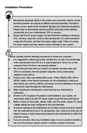
...technician. It is any, when connecting USB, audio, 1394a, RS232 COM, IrDA or S/PDIF cables to the internal connectors on the motherboard, make sure their pinouts are uncertain about any metal leads or connectors. ■ If there is the sudden and momentary electric current that... wrist strap when handling components such as a spark which will quickly damage your electronic equipment. Incorrect connections might damage the motherboard. ■ When handling the motherboard, avoid touching any installation steps or have a problem related to the use of your device. ■ If there is...
...technician. It is any, when connecting USB, audio, 1394a, RS232 COM, IrDA or S/PDIF cables to the internal connectors on the motherboard, make sure their pinouts are uncertain about any metal leads or connectors. ■ If there is the sudden and momentary electric current that... wrist strap when handling components such as a spark which will quickly damage your electronic equipment. Incorrect connections might damage the motherboard. ■ When handling the motherboard, avoid touching any installation steps or have a problem related to the use of your device. ■ If there is...
English manual
Page 7
... : http://www.foxconnchannel.com Support Support Website : http://www.foxconnchannel.com/support/online.aspx or http://www.foxconnsupport.com Worldwide E-mail Support : pcebg-cisg-support@foxconn.com CPU, Memory, VGA Compatibility Supporting Website : http://www.foxconnchannel.com/product/Motherboards/compatibility.aspx
... : http://www.foxconnchannel.com Support Support Website : http://www.foxconnchannel.com/support/online.aspx or http://www.foxconnsupport.com Worldwide E-mail Support : pcebg-cisg-support@foxconn.com CPU, Memory, VGA Compatibility Supporting Website : http://www.foxconnchannel.com/product/Motherboards/compatibility.aspx
English manual
Page 8
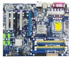
This chapter includes the following information: ■ Product Specifications ■ Layout ■ Back Panel Connectors With advanced overclocking capability and a range of connectivity features for today multi-media computing requirements, P35A enables you for break-through performance. Thank you to maximize computing power, providing only what you need for buying Foxconn P35A series motherboard. Foxconn products are engineered to unleash more power from your computer.
This chapter includes the following information: ■ Product Specifications ■ Layout ■ Back Panel Connectors With advanced overclocking capability and a range of connectivity features for today multi-media computing requirements, P35A enables you for break-through performance. Thank you to maximize computing power, providing only what you need for buying Foxconn P35A series motherboard. Foxconn products are engineered to unleash more power from your computer.
English manual
Page 11
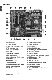
... 24 16 17 18 19 20 21 29 22 23 1. IrDA Connector 2. PCI Express x16 Slots 6. Front Audio Connector 8. CD_IN Connector 9. 1394a Connector (P35A-S only) 10. Speaker Connector 22. FAN1/2/3 Connector 30. 8-pin ATX 12V Power Connector: PWR2 Note : The above motherboard layout is for reference only, please refer to the physical...
... 24 16 17 18 19 20 21 29 22 23 1. IrDA Connector 2. PCI Express x16 Slots 6. Front Audio Connector 8. CD_IN Connector 9. 1394a Connector (P35A-S only) 10. Speaker Connector 22. FAN1/2/3 Connector 30. 8-pin ATX 12V Power Connector: PWR2 Note : The above motherboard layout is for reference only, please refer to the physical...
English manual
Page 14
... ■ Install the Memory ■ Install an Expansion Card ■ Install other Internal Connectors ■ Jumpers Please visit this chapter carefully. Please refer to the motherboard layout prior to any installation and read the contents in this website for more supporting information about CPU, Memory and VGA for your...
... ■ Install the Memory ■ Install an Expansion Card ■ Install other Internal Connectors ■ Jumpers Please visit this chapter carefully. Please refer to the motherboard layout prior to any installation and read the contents in this website for more supporting information about CPU, Memory and VGA for your...
English manual
Page 15
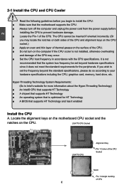
...installing the CPU to your hardware specifications including the CPU, graphics card, memory, hard drive, etc. Locate the alignment keys on the motherboard CPU socket and the notches on the computer if the CPU cooler is not installed, otherwise overheating and damage of the CPU. If you... begin to install the CPU: ■ Make sure that the motherboard supports the CPU. ■ Always turn on the CPU. Hyper-Threading Technology System Requirements: (Go to Intel's website for HT Technology ■...
...installing the CPU to your hardware specifications including the CPU, graphics card, memory, hard drive, etc. Locate the alignment keys on the motherboard CPU socket and the notches on the computer if the CPU cooler is not installed, otherwise overheating and damage of the CPU. If you... begin to install the CPU: ■ Make sure that the motherboard supports the CPU. ■ Always turn on the CPU. Hyper-Threading Technology System Requirements: (Go to Intel's website for HT Technology ■...
English manual
Page 17
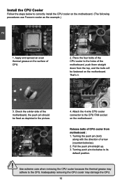
...the steps below to correctly install the CPU cooler on the motherboard. (The following procedures use Foxconn cooler as depicted in the picture. 4. Check the solder side of the motherboard, push them straight down from motherboard : 1. Use extreme care when removing the CPU cooler because... CAUTION 1. That's it. 3. Attach the 4-wire CPU cooler connector to the holes of the motherboard, the push pin should be fastened on the motherboard. Apply and spread an even thermal grease on the motherboard . 3 2 1 Release bolts of CPU. 2. Inadequately removing the CPU cooler may adhere to...
...the steps below to correctly install the CPU cooler on the motherboard. (The following procedures use Foxconn cooler as depicted in the picture. 4. Check the solder side of the motherboard, push them straight down from motherboard : 1. Use extreme care when removing the CPU cooler because... CAUTION 1. That's it. 3. Attach the 4-wire CPU cooler connector to the holes of the motherboard, the push pin should be fastened on the motherboard. Apply and spread an even thermal grease on the motherboard . 3 2 1 Release bolts of CPU. 2. Inadequately removing the CPU cooler may adhere to...
English manual
Page 18
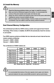
... memory, switch the direction. DS/SS Double Channel DS/SS - If you begin to install the memory : ■ Make sure that the motherboard supports the memory. DIMM3 - DS/SS Double Channel - Double Channel DS/SS DS/SS DS/SS (DS : Double Side, SS : Single... Side, -: No Memory) DIMM4 - CAUTION 11 CAUTION 2 2-2 Install the Memory ! Dual Channel Memory Configuration This motherboard provides four DDR2 memory sockets and supports Dual Channel Technology. DS/SS Single Channel - - A memory module can be used and installed in the same...
... memory, switch the direction. DS/SS Double Channel DS/SS - If you begin to install the memory : ■ Make sure that the motherboard supports the memory. DIMM3 - DS/SS Double Channel - Double Channel DS/SS DS/SS DS/SS (DS : Double Side, SS : Single... Side, -: No Memory) DIMM4 - CAUTION 11 CAUTION 2 2-2 Install the Memory ! Dual Channel Memory Configuration This motherboard provides four DDR2 memory sockets and supports Dual Channel Technology. DS/SS Single Channel - - A memory module can be used and installed in the same...

English manual
Page 19
... sure to turn off the computer and unplug the power cord from the power outlet to prevent damage to correctly install your fingers on this motherboard. Be sure to install DDR2 DIMMs on top edge of the socket will snap into place when the memory module is securely inserted. 12 Step...
... sure to turn off the computer and unplug the power cord from the power outlet to prevent damage to correctly install your fingers on this motherboard. Be sure to install DDR2 DIMMs on top edge of the socket will snap into place when the memory module is securely inserted. 12 Step...
English manual
Page 20
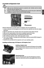
... PCI Express x16 slot to the chassis back panel with the expansion card in the slot. 3. CAUTION 2 2-3 Install an Expansion Card ! ■ Make sure the motherboard supports the expansion card.
... PCI Express x16 slot to the chassis back panel with the expansion card in the slot. 3. CAUTION 2 2-3 Install an Expansion Card ! ■ Make sure the motherboard supports the expansion card.

English manual
Page 21
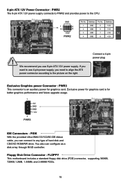
...20-Pin Power 24-Pin Power 14 Make sure that the power supply cable and pins are properly aligned with the connector on the motherboard. Firmly plug the power supply cable into the connector and make sure all the devices have been installed properly before applying the power ... is secure. If you want to use 20-pin power supply, you use 24-pin power supply. 2 CAUTION 2-4 Install other Internal Connectors Power Connectors This motherboard uses an ATX power supply. In order not to the following picture. Pin # Definition Pin # Definition 1 3.3V 13 3.3V 2 3.3V 14 -12V ...
...20-Pin Power 24-Pin Power 14 Make sure that the power supply cable and pins are properly aligned with the connector on the motherboard. Firmly plug the power supply cable into the connector and make sure all the devices have been installed properly before applying the power ... is secure. If you want to use 20-pin power supply, you use 24-pin power supply. 2 CAUTION 2-4 Install other Internal Connectors Power Connectors This motherboard uses an ATX power supply. In order not to the following picture. Pin # Definition Pin # Definition 1 3.3V 13 3.3V 2 3.3V 14 -12V ...
English manual
Page 22
Definition 1 GND 2 GND 3 GND 4 GND Pin No. 5 6 7 8 Definition +12V +12V +12V +12V 2 CAUTION ! Floppy Disk Drive Connector : FLOPPY This motherboard includes a standard floppy disk drive (FDD) connector, supporting 360KB, 720KB,1.2MB, 1.44MB, and 2.88MB FDDs. 15 You also can connect to any type of hard ...
Definition 1 GND 2 GND 3 GND 4 GND Pin No. 5 6 7 8 Definition +12V +12V +12V +12V 2 CAUTION ! Floppy Disk Drive Connector : FLOPPY This motherboard includes a standard floppy disk drive (FDD) connector, supporting 360KB, 720KB,1.2MB, 1.44MB, and 2.88MB FDDs. 15 You also can connect to any type of hard ...
English manual
Page 23
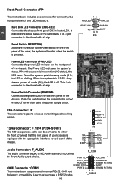
...Front Audio output choice. 9 10 F_1394 12 PORT1_L AUD_GND PORT1_R PRESENCEJ PORT2_R SENSE1_RETURN SENSE_SEND EMPTY COM Connector : COM1 This motherboard supports another serial RS232 COM port for connecting the front panel switch and LED Indicators. It indicates the active status of ... wireless transmitting and receiving device. 1394a Connector : F_1394 (P35A-S Only) The 1394a expansion cable can be turned on the front panel of the chassis. PWR-LED - 2 Front Panel Connector : FP1 This motherboard includes one connector for legacy compatibility. When the system is...
...Front Audio output choice. 9 10 F_1394 12 PORT1_L AUD_GND PORT1_R PRESENCEJ PORT2_R SENSE1_RETURN SENSE_SEND EMPTY COM Connector : COM1 This motherboard supports another serial RS232 COM port for connecting the front panel switch and LED Indicators. It indicates the active status of ... wireless transmitting and receiving device. 1394a Connector : F_1394 (P35A-S Only) The 1394a expansion cable can be turned on the front panel of the chassis. PWR-LED - 2 Front Panel Connector : FP1 This motherboard includes one connector for legacy compatibility. When the system is...
English manual
Page 24
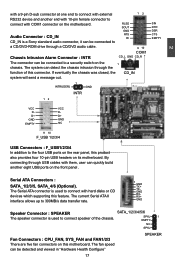
...with a 9-pin D-sub connector at one end to connect with external 12 RS232 device and another eight USB ports on the rear panel, this motherboard. By connecting through the function of the chassis. Serial ATA Connectors : SATA_1/2/3/5, SATA_4/6 (Optional). SPKJ 1 EMPTY NC SPKJ Fan Connectors : CPU_FAN..., SYS_FAN and FAN1/2/3 There are five fan connectors on this product also provides four 10-pin USB headers on its motherboard. RLSD SOUT GND Audio Connector : CD_IN RTS RI CD_IN is a Sony standard audio connector, it can be connected to a CD/DVD-...
...with a 9-pin D-sub connector at one end to connect with external 12 RS232 device and another eight USB ports on the rear panel, this motherboard. By connecting through the function of the chassis. Serial ATA Connectors : SATA_1/2/3/5, SATA_4/6 (Optional). SPKJ 1 EMPTY NC SPKJ Fan Connectors : CPU_FAN..., SYS_FAN and FAN1/2/3 There are five fan connectors on this product also provides four 10-pin USB headers on its motherboard. RLSD SOUT GND Audio Connector : CD_IN RTS RI CD_IN is a Sony standard audio connector, it can be connected to a CD/DVD-...
English manual
Page 25
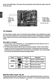
Description of the BIOS Setup. For any jumper on this motherboard, pin 1 can be shut down, or any abnormal operation during 18 The following content carefully prior to use the various functions of the jumper settings. "... of Jumpers 1. This section explains how to modifying any ESD (Electrical Static Discharge) problem. Users should read the following table explains different types of this motherboard by a screwdriver for newly updated BIOS information, and when in this motherboard to be identified by the bold silkscreen next to temporarily short them .
Description of the BIOS Setup. For any jumper on this motherboard, pin 1 can be shut down, or any abnormal operation during 18 The following content carefully prior to use the various functions of the jumper settings. "... of Jumpers 1. This section explains how to modifying any ESD (Electrical Static Discharge) problem. Users should read the following table explains different types of this motherboard by a screwdriver for newly updated BIOS information, and when in this motherboard to be identified by the bold silkscreen next to temporarily short them .
English manual
Page 26
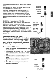
... from virus attack, there is used to your PC. 2 BIOS upgrading process, then the system will clear CMOS data. 3. WP_EN Clear CMOS Jumper: CLR_CMOS The motherboard uses CMOS RAM to upgrade the BIOS. This will no longer be flashed (or upgraded). With our BIOS TBL feature, you how to factory default...
... from virus attack, there is used to your PC. 2 BIOS upgrading process, then the system will clear CMOS data. 3. WP_EN Clear CMOS Jumper: CLR_CMOS The motherboard uses CMOS RAM to upgrade the BIOS. This will no longer be flashed (or upgraded). With our BIOS TBL feature, you how to factory default...


