English Manual
Page 10
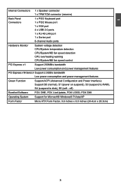
1 Internal Connectors 1 x Speaker connector 1 x TPM/TCM connector (reserve) Back Panel 1 x PS/2 Keyboard port Connectors 1 x PS/2 Mouse port 1 x VGA port 4 x USB 2.0 ports 1 x RJ-45 LAN port 1 x Series port 6-channel Audio ports Hardware Monitor System voltage detection CPU/System temperature detection CPU/System/NB fan speed detection CPU overheating warning CPU/System/NB fan speed control PCI Express x1 Support 250MB/s bandwidth Low power consumption and power management features PCI Express x16 Gen2.0 Support 2.5GB/s bandwidth Low power consumption and power ...
1 Internal Connectors 1 x Speaker connector 1 x TPM/TCM connector (reserve) Back Panel 1 x PS/2 Keyboard port Connectors 1 x PS/2 Mouse port 1 x VGA port 4 x USB 2.0 ports 1 x RJ-45 LAN port 1 x Series port 6-channel Audio ports Hardware Monitor System voltage detection CPU/System temperature detection CPU/System/NB fan speed detection CPU overheating warning CPU/System/NB fan speed control PCI Express x1 Support 250MB/s bandwidth Low power consumption and power management features PCI Express x16 Gen2.0 Support 2.5GB/s bandwidth Low power consumption and power ...
English Manual
Page 14
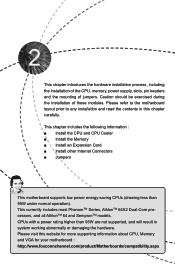
...; Install the Memory ■ Install an Expansion Card ■ Install other Internal Connectors ■ Jumpers This motherboard supports low power energy-saving CPUs (drawing less than 95W are not supported, and will result in this website for more supporting information about CPU, Memory and VGA for your motherboard : http://www.foxconnchannel.com/product/Motherboards/compatibility.aspx This currently includes most PhenomTM Series, AthlonTM 64X2 Dual-Core processors, and all AthlonTM 64 and SempronTM models...
...; Install the Memory ■ Install an Expansion Card ■ Install other Internal Connectors ■ Jumpers This motherboard supports low power energy-saving CPUs (drawing less than 95W are not supported, and will result in this website for more supporting information about CPU, Memory and VGA for your motherboard : http://www.foxconnchannel.com/product/Motherboards/compatibility.aspx This currently includes most PhenomTM Series, AthlonTM 64X2 Dual-Core processors, and all AthlonTM 64 and SempronTM models...

English Manual
Page 19
... graphics card is fully seated in the expansion slot. 1. Secure the card's metal bracket to release the card and then pull the card straight up from the chassis back panel. 2. Install the driver provided with your card. After installing all expansion cards, replace the chassis cover. 6. PCI Express x1 PCI Express x16 PCI Follow the steps below to make any required BIOS changes for your expansion card in the slot. 3. If necessary, go to BIOS Setup...
... graphics card is fully seated in the expansion slot. 1. Secure the card's metal bracket to release the card and then pull the card straight up from the chassis back panel. 2. Install the driver provided with your card. After installing all expansion cards, replace the chassis cover. 6. PCI Express x1 PCI Express x16 PCI Follow the steps below to make any required BIOS changes for your expansion card in the slot. 3. If necessary, go to BIOS Setup...
English Manual
Page 21
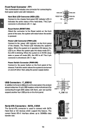
... sleep mode (S1) , the LED is pressed. This 2-pin connector is directional with +/- Push this feature. This 2-pin connector is used to be turned on the front panel. 12 VCC VCC D- RESET-SW PWR-SW NC EMPTY 9 10 FP1 USB Connectors : F_USB1/2 In addition to the chassis front panel IDE indicator LED. Power Switch Connector (PWR-SW) Connect to the Reset switch on the front panel of the case; By connecting through USB cables with SATA Hard Disk or CD devices which support...
... sleep mode (S1) , the LED is pressed. This 2-pin connector is directional with +/- Push this feature. This 2-pin connector is used to be turned on the front panel. 12 VCC VCC D- RESET-SW PWR-SW NC EMPTY 9 10 FP1 USB Connectors : F_USB1/2 In addition to the chassis front panel IDE indicator LED. Power Switch Connector (PWR-SW) Connect to the Reset switch on the front panel of the case; By connecting through USB cables with SATA Hard Disk or CD devices which support...

English Manual
Page 23
... to BIOS Setup to use the various functions of Jumpers 1. For any jumper setting. Jumper 1 Diagram 1 1 Definition 1-2 2-3 Description Set Pin 1 and Pin 2 closed Set Pin 2 and Pin 3 closed . 4. Clear CMOS data is recommended. This section explains how to configure new system as "1". 2. This will clear CMOS data. 3. Remove jumper cap from the power outlet. 2. Normal 1 2 (Default) 3 CLR_CMOS ■ Disconnect the power cable before adjusting the jumper settings. ■ Do not clear the CMOS while the system is turned on this motherboard...
... to BIOS Setup to use the various functions of Jumpers 1. For any jumper setting. Jumper 1 Diagram 1 1 Definition 1-2 2-3 Description Set Pin 1 and Pin 2 closed Set Pin 2 and Pin 3 closed . 4. Clear CMOS data is recommended. This section explains how to configure new system as "1". 2. This will clear CMOS data. 3. Remove jumper cap from the power outlet. 2. Normal 1 2 (Default) 3 CLR_CMOS ■ Disconnect the power cable before adjusting the jumper settings. ■ Do not clear the CMOS while the system is turned on this motherboard...
English Manual
Page 26
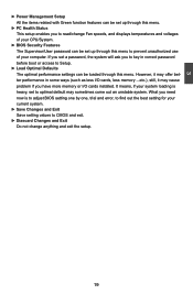
... CMOS and exit. ► Diascard Changes and Exit Do not change Fan speeds, and displays temperatures and voltages of your CPU/System. ► BIOS Security Features The Supervisor/User password can be set to optimal default may offer better performance in correct password before boot or access to Setup. ► Load Optimal Defaults The optimal performance settings can be set up through this menu. ► PC Health Status This setup enables you to prevent unauthorized use...
... CMOS and exit. ► Diascard Changes and Exit Do not change Fan speeds, and displays temperatures and voltages of your CPU/System. ► BIOS Security Features The Supervisor/User password can be set to optimal default may offer better performance in correct password before boot or access to Setup. ► Load Optimal Defaults The optimal performance settings can be set up through this menu. ► PC Health Status This setup enables you to prevent unauthorized use...

English Manual
Page 27
... displays the current BIOS version. Use [ENTER], [TAB] or [SHIFT-TAB] to 12. User can enable or disable the related mode and technology for the relevant device. System Information This sub-menu is automatically displayed by users. CMOS Setup Utility - Day-weekday from 1 to select a field. Year-year, set up by BIOS (Read Only). Halt On [All, But Keyboard] Model Name : M61PML/M61PML-K BIOS Version : AC1F1B06 BIOS Release Date : 01/05/2011 CPU Name : AMD Engineering Sample Total Memory SIze...
... displays the current BIOS version. Use [ENTER], [TAB] or [SHIFT-TAB] to 12. User can enable or disable the related mode and technology for the relevant device. System Information This sub-menu is automatically displayed by users. CMOS Setup Utility - Day-weekday from 1 to select a field. Year-year, set up by BIOS (Read Only). Halt On [All, But Keyboard] Model Name : M61PML/M61PML-K BIOS Version : AC1F1B06 BIOS Release Date : 01/05/2011 CPU Name : AMD Engineering Sample Total Memory SIze...
English Manual
Page 32
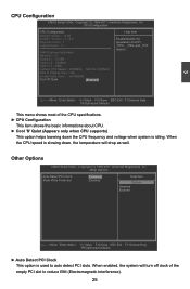
... only when CPU supports) This option helps lowering down , the temperature will turn off clock of ACPI Logical Count : 4 _PPC, _PSS, and _PCT objects . Other Options CMOS Setup Utility - Other Options Auto Detect PCI Clock Flash Write Protection [Disabled] [Disable] Help Item Options Disabled Enabled Move Enter:Select +/-/:Value F10:Save ESC:Exit F1:General Help F9:Optimized Defaults ► Auto Detect PCI Clock This option is idling. 3 CPU Configuration CMOS Setup Utility - CPU Configuration CPU Configuration Help Item Module Version : 13...
... only when CPU supports) This option helps lowering down , the temperature will turn off clock of ACPI Logical Count : 4 _PPC, _PSS, and _PCT objects . Other Options CMOS Setup Utility - Other Options Auto Detect PCI Clock Flash Write Protection [Disabled] [Disable] Help Item Options Disabled Enabled Move Enter:Select +/-/:Value F10:Save ESC:Exit F1:General Help F9:Optimized Defaults ► Auto Detect PCI Clock This option is idling. 3 CPU Configuration CMOS Setup Utility - CPU Configuration CPU Configuration Help Item Module Version : 13...
English Manual
Page 36
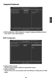
...SATA Configuration SATA Configuration Help Item OnBoard SATA Controller OnBoard SATA Mode [Enable d] [IDE ] IDE RAID Move Enter:Select +/-/:Value F10:Save ESC:Exit F1:General Help F9:Optimized Defaults ► OnBoard SATA Controller This item is used to enable or disable the onboard SATA controller. ► OnBoard SATA Mode This item allows you to relative submenu. Copyright (C) 1985-2011, American Megatrends, Inc. Integrated Peripherals ► SATA Configuration ► USB Configuration ► SuperIO Configuration ► OnBoard Devices...
...SATA Configuration SATA Configuration Help Item OnBoard SATA Controller OnBoard SATA Mode [Enable d] [IDE ] IDE RAID Move Enter:Select +/-/:Value F10:Save ESC:Exit F1:General Help F9:Optimized Defaults ► OnBoard SATA Controller This item is used to enable or disable the onboard SATA controller. ► OnBoard SATA Mode This item allows you to relative submenu. Copyright (C) 1985-2011, American Megatrends, Inc. Integrated Peripherals ► SATA Configuration ► USB Configuration ► SuperIO Configuration ► OnBoard Devices...
English Manual
Page 37
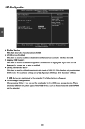
... Storage Configuration After pressing , you have a USB keyboard or mouse, set to auto or enabled. ► USB 2.0 Controller Mode This item is used to enable the support for legacy USB. USB Devices Enabled : Auto option disables None legacy support if no USB devices are : [High Speed] in 480Mbps; [Full Speed] in 12Mbps. 3 USB Configuration CMOS Setup Utility - The available settings are Legacy USB Support [Enabled] commected. USB Configuration USB Configuration Help Item Module Version - 2.24.5-13.4 Enable support for USB devices on legacy...
... Storage Configuration After pressing , you have a USB keyboard or mouse, set to auto or enabled. ► USB 2.0 Controller Mode This item is used to enable the support for legacy USB. USB Devices Enabled : Auto option disables None legacy support if no USB devices are : [High Speed] in 480Mbps; [Full Speed] in 12Mbps. 3 USB Configuration CMOS Setup Utility - The available settings are Legacy USB Support [Enabled] commected. USB Configuration USB Configuration Help Item Module Version - 2.24.5-13.4 Enable support for USB devices on legacy...
English Manual
Page 39
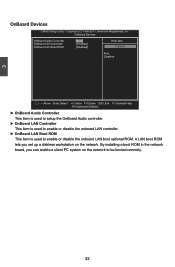
... OnBoard Audio Controller [Auto] Help Item OnBoard LAN Controller OnBoard LAN Boot ROM [Enabled] [Disabled] Options Auto Disabled Move Enter:Select +/-/:Value F10:Save ESC:Exit F1:General Help F9:Optimized Defaults ► OnBoard Audio Controller This item is used to setup the OnBoard Audio controller. ► OnBoard LAN Controller This item is used to enable or disable the onboard LAN controller. ► OnBoard LAN Boot ROM This item is used to be booted remotely. 32 By installing a boot ROM in the network board, you set...
... OnBoard Audio Controller [Auto] Help Item OnBoard LAN Controller OnBoard LAN Boot ROM [Enabled] [Disabled] Options Auto Disabled Move Enter:Select +/-/:Value F10:Save ESC:Exit F1:General Help F9:Optimized Defaults ► OnBoard Audio Controller This item is used to setup the OnBoard Audio controller. ► OnBoard LAN Controller This item is used to enable or disable the onboard LAN controller. ► OnBoard LAN Boot ROM This item is used to be booted remotely. 32 By installing a boot ROM in the network board, you set...

English Manual
Page 40
... some CPU and L2 configuration context. Power Management Setup CMOS Setup Utility - Copyright (C) 1985-2011, American Megatrends, Inc. The S1 sleeping state is a low wake latency sleeping state. Control starts from the processor's reset vector after PWR-Fail [S3 (STR)] Help Item [Disabled] [Disabled] Select the ACPI [Disabled] State used for [Enabled] System Suspend. [Enabled] [Enabled] [Disabled] [Enabled] [Power Off] 3 Move Enter:Select +/-/:Value F10:Save ESC:Exit F1:General Help F9:Optimized Defaults ACPI (Advanced Configuration and Power Interface...
... some CPU and L2 configuration context. Power Management Setup CMOS Setup Utility - Copyright (C) 1985-2011, American Megatrends, Inc. The S1 sleeping state is a low wake latency sleeping state. Control starts from the processor's reset vector after PWR-Fail [S3 (STR)] Help Item [Disabled] [Disabled] Select the ACPI [Disabled] State used for [Enabled] System Suspend. [Enabled] [Enabled] [Disabled] [Enabled] [Power Off] 3 Move Enter:Select +/-/:Value F10:Save ESC:Exit F1:General Help F9:Optimized Defaults ACPI (Advanced Configuration and Power Interface...

English Manual
Page 43
... item is used to install or change the password. BIOS Security Features Security Settings Help Item Supervisor Password : Not Installed User Password : Not Installed Change Supervisor Password [Press Enter] Boot Sector Virus Protection [Disabled] Enter or change supervisor password. 3 This item is used to set a slope value in PWM/Temperature diagram. The default value is used to the temperature input value by linear changing. Enter New Password : If you have installed the Supervisor Password, the following items will start to...
... item is used to install or change the password. BIOS Security Features Security Settings Help Item Supervisor Password : Not Installed User Password : Not Installed Change Supervisor Password [Press Enter] Boot Sector Virus Protection [Disabled] Enter or change supervisor password. 3 This item is used to set a slope value in PWM/Temperature diagram. The default value is used to the temperature input value by linear changing. Enter New Password : If you have installed the Supervisor Password, the following items will start to...

English Manual
Page 46
... put it into your CD/DVD-ROM drive, and the main menu will be displayed on your system without going to improve (or overclock) your PC screen to guide you need to install all the drivers have been installed. CIR Device Driver 2. Adobe Acrobat Reader G. Adobe Acrobat Reader H. FOX DMI F. Browser Configuration Utility B. Software Utilities Use these options to restart your computer after all the drivers for your system. FOX LOGO...
... put it into your CD/DVD-ROM drive, and the main menu will be displayed on your system without going to improve (or overclock) your PC screen to guide you need to install all the drivers have been installed. CIR Device Driver 2. Adobe Acrobat Reader G. Adobe Acrobat Reader H. FOX DMI F. Browser Configuration Utility B. Software Utilities Use these options to restart your computer after all the drivers for your system. FOX LOGO...

English Manual
Page 47
... er's Manual Choose the items you want to install, or you can simply put it into your DVD-ROM drive, and the main menu will be displayed on each individual driver to install it manually. You must click "NVIDIA Chipset Driver" to install it first. 4 Install Driver and Utility This motherboard comes with one DVD, after installing the Operating System, you can click on your PC screen to guide you how to install. 1.
... er's Manual Choose the items you want to install, or you can simply put it into your DVD-ROM drive, and the main menu will be displayed on each individual driver to install it manually. You must click "NVIDIA Chipset Driver" to install it first. 4 Install Driver and Utility This motherboard comes with one DVD, after installing the Operating System, you can click on your PC screen to guide you how to install. 1.
English Manual
Page 72
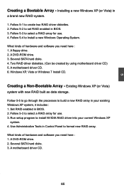
... BIOS. 3. Follow 5-4 to format new RAID array. A floppy drive. 2. Set RAID enabled in a brand new RAID system. 1. 5 Creating a Bootable Array - Several SATA hard disks. 4. A motherboard driver CD. 6. Use Administrative Tools in your current Windows XP system. 4. A DVD-ROM drive. 2. Two RAID driver diskettes. (Can be created by using motherboard driver CD) 5. Creating a Non-Bootable Array - A motherboard driver CD. 65 Run setup program to create two RAID driver diskettes. 2. Existing Windows XP (or Vista) system with new RAID built as data storage...
... BIOS. 3. Follow 5-4 to format new RAID array. A floppy drive. 2. Set RAID enabled in a brand new RAID system. 1. 5 Creating a Bootable Array - Several SATA hard disks. 4. A motherboard driver CD. 6. Use Administrative Tools in your current Windows XP system. 4. A DVD-ROM drive. 2. Two RAID driver diskettes. (Can be created by using motherboard driver CD) 5. Creating a Non-Bootable Array - A motherboard driver CD. 65 Run setup program to create two RAID driver diskettes. 2. Existing Windows XP (or Vista) system with new RAID built as data storage...

English Manual
Page 90
... disk labeled manufacturer-supplied hardware support disk into your floppy drive. It will load support for the following picture appears, press [S] to insert the RAID driver diskette 1 into Drive A: * Press ENTER when ready Enter=Continue ESC=Cancel F3=Exit 83 Windows Setup Setup could not determine the type of one or more mass storage devices installed in your system, the following mass storage device(s): * To specify additional SCSI adapters, CD-ROM drivers, or special disk controllers...
... disk labeled manufacturer-supplied hardware support disk into your floppy drive. It will load support for the following picture appears, press [S] to insert the RAID driver diskette 1 into Drive A: * Press ENTER when ready Enter=Continue ESC=Cancel F3=Exit 83 Windows Setup Setup could not determine the type of one or more mass storage devices installed in your system, the following mass storage device(s): * To specify additional SCSI adapters, CD-ROM drivers, or special disk controllers...

English Manual
Page 91
... mass storage devices for use with Windows, press ENTER. As we need to install both two drivers, so we wanted. There are two drivers, all these two drivers must be installed. Windows Setup You have a device support disk from the following mass storage device(s): NVIDIA RAID Driver (required) * To specify additional SCSI adapters, CD-ROM drivers, or special disk controllers for use with Windows, including those for use with Windows, using a device support disk provided by an adapter manufacturer. Press [Enter] to configure...
... mass storage devices for use with Windows, press ENTER. As we need to install both two drivers, so we wanted. There are two drivers, all these two drivers must be installed. Windows Setup You have a device support disk from the following mass storage device(s): NVIDIA RAID Driver (required) * To specify additional SCSI adapters, CD-ROM drivers, or special disk controllers for use with Windows, including those for use with Windows, using a device support disk provided by an adapter manufacturer. Press [Enter] to configure...

English Manual
Page 95
... Setup copies files from RAID floppy diskette 2 to the Windows installation folders, it is done. Windows Setup Insert the disk labeled : NVIDIA RAID DRIVER (SCSI) disk 2 into drive A: * Press ENTER when ready. 5 F3=Quit Enter=Continue 16. F3=Quit Enter=Continue 17. Windows Setup Insert the disk labeled : NVIDIA RAID DRIVER (SCSI) disk 1 into drive A: * Press ENTER when ready. Press [Enter] to insert the second RAID diskette into floppy drive again. After Setup copies files from RAID floppy diskette 1 to the Windows installation folders...
... Setup copies files from RAID floppy diskette 2 to the Windows installation folders, it is done. Windows Setup Insert the disk labeled : NVIDIA RAID DRIVER (SCSI) disk 2 into drive A: * Press ENTER when ready. 5 F3=Quit Enter=Continue 16. F3=Quit Enter=Continue 17. Windows Setup Insert the disk labeled : NVIDIA RAID DRIVER (SCSI) disk 1 into drive A: * Press ENTER when ready. Press [Enter] to insert the second RAID diskette into floppy drive again. After Setup copies files from RAID floppy diskette 1 to the Windows installation folders...
English Manual
Page 96
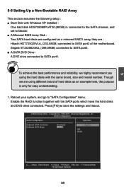
... array, they are : Hitachi HDT725025VLA, (232.88GB) connected to save the settings and reboot. SATA Configuration SATA Configuration Help Item OnBoard SATA Controller [Enabled] Options OnBoard SATA Mode [RAID] IDE RAID Move Enter:Select +/-/:Value F10:Save ESC:Exit F1:General Help F9:Optimized Defaults 89 5 5-5 Setting Up a Non-Bootable RAID Array This section assumes the following setup : ■ Boot Disk with Windows XP installed : One hard disk HDS728080PLAT20 (80GB) is only for easy...
... array, they are : Hitachi HDT725025VLA, (232.88GB) connected to save the settings and reboot. SATA Configuration SATA Configuration Help Item OnBoard SATA Controller [Enabled] Options OnBoard SATA Mode [RAID] IDE RAID Move Enter:Select +/-/:Value F10:Save ESC:Exit F1:General Help F9:Optimized Defaults 89 5 5-5 Setting Up a Non-Bootable RAID Array This section assumes the following setup : ■ Boot Disk with Windows XP installed : One hard disk HDS728080PLAT20 (80GB) is only for easy...


