English Manual.
Page 10
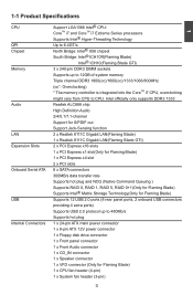
...® Hyper-Threading Technology QPI Up to 6.4GT/s Chipset North Bridge: Intel® X58 chipset South Bridge: Intel® ICH10R(Flaming Blade) Intel® ICH10(Flaming Blade GTI) Memory 3 x 240-pin DDR3 DIMM sockets Supports up to CPU. Intel officially only...2/4/5.1/7.1-channel Support for S/PDIF out Support Jack-Sensing function LAN 2 x Realtek 8111C Gigabit LAN(Flaming Blade) 1 x Realtek 8111C Gigabit LAN(Flaming Blade GTI) Expansion Slots 2 x PCI Express x16 slots 1 x PCI Express x1 slot(Only for Flaming Blade) 1 x PCI Express x4 slot 2 x PCI...
...® Hyper-Threading Technology QPI Up to 6.4GT/s Chipset North Bridge: Intel® X58 chipset South Bridge: Intel® ICH10R(Flaming Blade) Intel® ICH10(Flaming Blade GTI) Memory 3 x 240-pin DDR3 DIMM sockets Supports up to CPU. Intel officially only...2/4/5.1/7.1-channel Support for S/PDIF out Support Jack-Sensing function LAN 2 x Realtek 8111C Gigabit LAN(Flaming Blade) 1 x Realtek 8111C Gigabit LAN(Flaming Blade GTI) Expansion Slots 2 x PCI Express x16 slots 1 x PCI Express x1 slot(Only for Flaming Blade) 1 x PCI Express x4 slot 2 x PCI...
English Manual.
Page 12
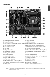
PCI Express x1 Slot(Only for Flaming Blade) 28. PCI Express x16 Slots Blade)/ Intel® ICH10(Flaming Blade GTI) 5. PCI Slots 21. 24-pin ATX Power Connector 7. VBAT_DISCHARGE Jumper Blade) 10. Reset Button(Only for Flaming Blade) 19. Debug LED 30. CD_IN ... 20 21 22 23 24 1. 8-pin ATX 12V Power Connector 17. IDE Connector 2. South Bridge: Intel® ICH10R(Flaming 4. North Bridge: Intel® X58 Chipset Note : The above motherboard layout is for reference only, please refer to the physical motherboard for Flaming Blade) 8. System Fan Header 18. PCI Express...
PCI Express x1 Slot(Only for Flaming Blade) 28. PCI Express x16 Slots Blade)/ Intel® ICH10(Flaming Blade GTI) 5. PCI Slots 21. 24-pin ATX Power Connector 7. VBAT_DISCHARGE Jumper Blade) 10. Reset Button(Only for Flaming Blade) 19. Debug LED 30. CD_IN ... 20 21 22 23 24 1. 8-pin ATX 12V Power Connector 17. IDE Connector 2. South Bridge: Intel® ICH10R(Flaming 4. North Bridge: Intel® X58 Chipset Note : The above motherboard layout is for reference only, please refer to the physical motherboard for Flaming Blade) 8. System Fan Header 18. PCI Express...

English Manual.
Page 46
... Control This item is used to set value, the system will shut down automatically. ► Core i7 CPU / X58 IOH / System Temperature These items show the Core i7 CPU / X58 IOH / System temperature detected automatically by the system. ► CPU Core / CPU VTT(Uncore) / DDR3 Memory...using Duty-Cycle. AwardBIOS CMOS Setup Utility Hardware Monitor Shutdown Temperature Core i7 CPU Temperature X58 I0H Temperature System Temperature CPU Core Voltage CPU VTT (Uncore) Voltage DDR3 Memory Voltage X58 IOH Core Voltage PSU 12V Rail PSU 3.3V Rail BIOS Battery 3V Voltage CPU Fan...
... Control This item is used to set value, the system will shut down automatically. ► Core i7 CPU / X58 IOH / System Temperature These items show the Core i7 CPU / X58 IOH / System temperature detected automatically by the system. ► CPU Core / CPU VTT(Uncore) / DDR3 Memory...using Duty-Cycle. AwardBIOS CMOS Setup Utility Hardware Monitor Shutdown Temperature Core i7 CPU Temperature X58 I0H Temperature System Temperature CPU Core Voltage CPU VTT (Uncore) Voltage DDR3 Memory Voltage X58 IOH Core Voltage PSU 12V Rail PSU 3.3V Rail BIOS Battery 3V Voltage CPU Fan...
English Manual.
Page 54
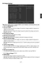
... DQ (Data) x 0.500 x DIMM2 Vref CA (Address) x 0.500 x DIMM2 Vref DQ (Data) x 0.500 x DIMM3 Vref CA (Address) x 0.500 x DIMM3 Vref DQ (Data) x 0.500 Chipset Voltages ********* x X58 IOH Core Voltage 1.10V Move Enter:Select +/-/PU/PD:Value F10:Save ESC:Exit F1:General Help F5:Previous Values F7:Optimized Defaults Note: When...
... DQ (Data) x 0.500 x DIMM2 Vref CA (Address) x 0.500 x DIMM2 Vref DQ (Data) x 0.500 x DIMM3 Vref CA (Address) x 0.500 x DIMM3 Vref DQ (Data) x 0.500 Chipset Voltages ********* x X58 IOH Core Voltage 1.10V Move Enter:Select +/-/PU/PD:Value F10:Save ESC:Exit F1:General Help F5:Previous Values F7:Optimized Defaults Note: When...
English Manual.
Page 55
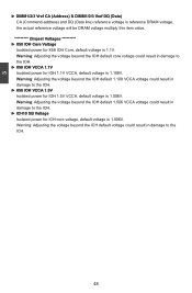
...default voltage is 1.506V. Warning: Adjusting the voltage beyond the IOH default 1.506 VCCA voltage could result in damage to the IOH. ► X58 IOH VCCA 1.5V Isolated power for IOH 1.5V VCCA, default voltage is 1.506V. Warning: Adjusting the voltage beyond the IOH default core voltage could... result in damage to the ICH. 48 Warning: Adjusting the voltage beyond the ICH default voltage could result in damage to the IOH. ► X58 IOH VCCA 1.1V Isolated power for IOH 1.1V VCCA, default voltage is 1.1V. 3 ► DIMM1/2/3 Vref CA (Address) & DIMM1/2/3 Vref DQ (Data...
...default voltage is 1.506V. Warning: Adjusting the voltage beyond the IOH default 1.506 VCCA voltage could result in damage to the IOH. ► X58 IOH VCCA 1.5V Isolated power for IOH 1.5V VCCA, default voltage is 1.506V. Warning: Adjusting the voltage beyond the IOH default core voltage could... result in damage to the ICH. 48 Warning: Adjusting the voltage beyond the ICH default voltage could result in damage to the IOH. ► X58 IOH VCCA 1.1V Isolated power for IOH 1.1V VCCA, default voltage is 1.1V. 3 ► DIMM1/2/3 Vref CA (Address) & DIMM1/2/3 Vref DQ (Data...