
User manual
Page 5
... discharge (ESD) wrist strap when handling components such as a spark which will quickly damage your system. ! Also, make sure the power supply AC input voltage setting has been configured to the local standard. ■ To prevent damage to the motherboard, do not allow screws to... unplug the AC power cord from the power supply outlet. CAUTION Installation Precautions WARNING! ■ Electrostatic discharge (ESD) is overclocked. It is any installation steps or have a problem...
... discharge (ESD) wrist strap when handling components such as a spark which will quickly damage your system. ! Also, make sure the power supply AC input voltage setting has been configured to the local standard. ■ To prevent damage to the motherboard, do not allow screws to... unplug the AC power cord from the power supply outlet. CAUTION Installation Precautions WARNING! ■ Electrostatic discharge (ESD) is overclocked. It is any installation steps or have a problem...

User manual
Page 14
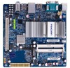
.... Caution should be exercised during the installation of jumpers. This chapter introduces the hardware and software installation process, including the installation of the CPU, memory, power supply, slots, pin headers and the mounting of these modules.
.... Caution should be exercised during the installation of jumpers. This chapter introduces the hardware and software installation process, including the installation of the CPU, memory, power supply, slots, pin headers and the mounting of these modules.

User manual
Page 16
... you using a 20-pin power supply, you need to align the ATX power connector according to the picture. 20-Pin Power 4-pin ATX 12 V Power Connector : PWR1 Connect the 4-pin ATX 12V power supply to PWR1 and provides power to damage any device, make sure it is the ATX power supply connector. Firmly plug the power supply cable into the connector and...
... you using a 20-pin power supply, you need to align the ATX power connector according to the picture. 20-Pin Power 4-pin ATX 12 V Power Connector : PWR1 Connect the 4-pin ATX 12V power supply to PWR1 and provides power to damage any device, make sure it is the ATX power supply connector. Firmly plug the power supply cable into the connector and...

User manual
Page 18
... the system's status. When the system is in S3/S4 sleep state or power off mode (S5), the LED is directional with +/- This 2-pin connector is off rather than using the power supply button. sign. Serial ATA Connectors : SATA_1/2 The Serial ATA connector is on... the front panel of the hard disks. Power Switch Connector (PWR-SW) Connect to the power LED indicator on the front panel of the chassis. sign....
... the system's status. When the system is in S3/S4 sleep state or power off mode (S5), the LED is directional with +/- This 2-pin connector is off rather than using the power supply button. sign. Serial ATA Connectors : SATA_1/2 The Serial ATA connector is on... the front panel of the hard disks. Power Switch Connector (PWR-SW) Connect to the power LED indicator on the front panel of the chassis. sign....


