
English Manual.
Page 6
... Install the Memory 10 Install an Expansion Card 12 Install other Internal Connectors 13 Jumpers 17 Chapter 3 BIOS Setup Enter BIOS Setup 19 Main Menu 19 System Information 21 Advanced BIOS Features 23 Fox Central Control Unit 25 Advanced Chipset Features 29 Integrated Peripherals 34 Power Management Setup 39... PC Health Status 41 BIOS Security Features 42 Load Optimal Defaults 43 Save & Exit Setup 43 Exit Without Saving 43 Chapter 4 CD Instruction Utility CD ...
... Install the Memory 10 Install an Expansion Card 12 Install other Internal Connectors 13 Jumpers 17 Chapter 3 BIOS Setup Enter BIOS Setup 19 Main Menu 19 System Information 21 Advanced BIOS Features 23 Fox Central Control Unit 25 Advanced Chipset Features 29 Integrated Peripherals 34 Power Management Setup 39... PC Health Status 41 BIOS Security Features 42 Load Optimal Defaults 43 Save & Exit Setup 43 Exit Without Saving 43 Chapter 4 CD Instruction Utility CD ...
English Manual.
Page 7
...66 FOX LOGO 67 FOX DMI 68 Chapter 5 RAID Configuration RAID Configuration Introduction 71 FastBuild Driver 73 Create a RAID Driver Diskette 75 RAID Enable in BIOS 77 Select a RAID Array for Use 77 Install a New Windows XP 90 Setting Up a Non-Bootable RAID Array 94 Technical Support : Website ...com Support Support Website : http://www.foxconnchannel.com/support/online.aspx or http://www.foxconnsupport.com Worldwide E-mail Support : pcebg-cisg-support@foxconn.com CPU, Memory, VGA Compatibility Supporting Website : http://www.foxconnchannel.com/product/Motherboards/compatibility.aspx
...66 FOX LOGO 67 FOX DMI 68 Chapter 5 RAID Configuration RAID Configuration Introduction 71 FastBuild Driver 73 Create a RAID Driver Diskette 75 RAID Enable in BIOS 77 Select a RAID Array for Use 77 Install a New Windows XP 90 Setting Up a Non-Bootable RAID Array 94 Technical Support : Website ...com Support Support Website : http://www.foxconnchannel.com/support/online.aspx or http://www.foxconnsupport.com Worldwide E-mail Support : pcebg-cisg-support@foxconn.com CPU, Memory, VGA Compatibility Supporting Website : http://www.foxconnchannel.com/product/Motherboards/compatibility.aspx
English Manual.
Page 17
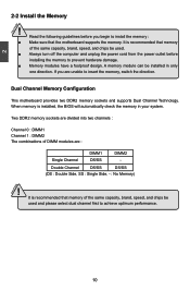
... following guidelines before installing the memory to achieve optimum performance. If you begin to insert the memory, switch the direction. When memory is installed, the BIOS will automatically check the memory in only one direction. CAUTION 10 A memory module can be installed in your system. Two DDR2 memory sockets are divided...
... following guidelines before installing the memory to achieve optimum performance. If you begin to insert the memory, switch the direction. When memory is installed, the BIOS will automatically check the memory in only one direction. CAUTION 10 A memory module can be installed in your system. Two DDR2 memory sockets are divided...
English Manual.
Page 19
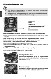
... the manual that supports your expansion card(s). 7. Turn on the card are completely inserted into the PCI Express x16 slot. If necessary, go to BIOS Setup to prevent hardware damage. Make sure the graphics card is fully seated in your expansion card. ■ Always turn off the computer and unplug... the power cord from the power outlet before installing an expansion card to make any required BIOS changes for your card. Install the driver provided with the slot, and press down on the card until it is locked by the latch at...
... the manual that supports your expansion card(s). 7. Turn on the card are completely inserted into the PCI Express x16 slot. If necessary, go to BIOS Setup to prevent hardware damage. Make sure the graphics card is fully seated in your expansion card. ■ Always turn off the computer and unplug... the power cord from the power outlet before installing an expansion card to make any required BIOS changes for your card. Install the driver provided with the slot, and press down on the card until it is locked by the latch at...
English Manual.
Page 23
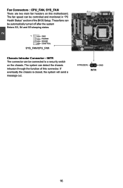
... S5 sleeping states. 1 GND POWER SENSE CONTROL SYS_FAN/CPU_FAN Chassis Intruder Connector : INTR The connector can detect the chassis intrusion through the function of the BIOS Setup.
... S5 sleeping states. 1 GND POWER SENSE CONTROL SYS_FAN/CPU_FAN Chassis Intruder Connector : INTR The connector can detect the chassis intrusion through the function of the BIOS Setup.
English Manual.
Page 24
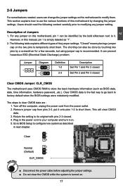
... the setting to its original with pins 2-3 closed Clear CMOS Jumper: CLR_CMOS The motherboard uses CMOS RAM to store the basic hardware information (such as BIOS data, date, time information, hardware password...etc.). Plug in next chapter. 1 Clear 2 3 WARNING! This section explains how to use the various... motherboard by a screwdriver for a few seconds, but using jumper cap is the fast way to go back to factory default when the BIOS settings were mistakenly modified. Description of the jumper settings. The shorting can also be identified by the bold silkscreen next to it. It ...
... the setting to its original with pins 2-3 closed Clear CMOS Jumper: CLR_CMOS The motherboard uses CMOS RAM to store the basic hardware information (such as BIOS data, date, time information, hardware password...etc.). Plug in next chapter. 1 Clear 2 3 WARNING! This section explains how to use the various... motherboard by a screwdriver for a few seconds, but using jumper cap is the fast way to go back to factory default when the BIOS settings were mistakenly modified. Description of the jumper settings. The shorting can also be identified by the bold silkscreen next to it. It ...
English Manual.
Page 25
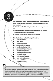
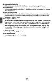
...Peripherals ■ Power Management Setup ■ PC Health Status ■ BIOS Security Features ■ Load Optimal Defaults ■ Save & Exit Setup ■ Exit Without Saving Since BIOS could be updated some other times, the BIOS information described in the future. This chapter tells how to change the ...on the screen during the system Power-On Self-Test (POST) process. 2. We do not guarantee the content of the BIOS parameters are also provided. This chapter includes the following cases occur: 1. Detailed descriptions of this manual will remain consistent with the newly...
...Peripherals ■ Power Management Setup ■ PC Health Status ■ BIOS Security Features ■ Load Optimal Defaults ■ Save & Exit Setup ■ Exit Without Saving Since BIOS could be updated some other times, the BIOS information described in the future. This chapter tells how to change the ...on the screen during the system Power-On Self-Test (POST) process. 2. We do not guarantee the content of the BIOS parameters are also provided. This chapter includes the following cases occur: 1. Detailed descriptions of this manual will remain consistent with the newly...
English Manual.
Page 26
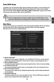
... this menu. Copyright (C) 1985-2006, American Megatrends, Inc. ► System Information ► PC Health Status ► Advanced BIOS Features ► BIOS Security Features ► Fox Central Control Unit Load Optimal Defaults ► Advanced Chipset Features Save & Exit Setup ► Integrated ...2006, American Megatrends, Inc. ► System Information It displays the basic system configuration, such as Serial I /O devices such as BIOS ID, CPU Name, memory size plus system date, time and Floppy drive. There are boot up settings. ► Fox Central Control...
... this menu. Copyright (C) 1985-2006, American Megatrends, Inc. ► System Information ► PC Health Status ► Advanced BIOS Features ► BIOS Security Features ► Fox Central Control Unit Load Optimal Defaults ► Advanced Chipset Features Save & Exit Setup ► Integrated ...2006, American Megatrends, Inc. ► System Information It displays the basic system configuration, such as Serial I /O devices such as BIOS ID, CPU Name, memory size plus system date, time and Floppy drive. There are boot up settings. ► Fox Central Control...
English Manual.
Page 27
... less I /O cards installed. What you have more memory or I /O cards, less memory ...etc.), still, it may cause problem if you need now is to adjust BIOS setting one by one, trial and error, to find out the best setting for your system loading is heavy, set up through this menu. ►... setting values to CMOS and exit. ► Exit Without Saving Do not change Fan speeds, and displays temperatures and voltages of your CPU/System. ► BIOS Security Features The Supervisor/User password can be set to prevent unauthorized use of your computer.
... less I /O cards installed. What you have more memory or I /O cards, less memory ...etc.), still, it may cause problem if you need now is to adjust BIOS setting one by one, trial and error, to find out the best setting for your system loading is heavy, set up through this menu. ►... setting values to CMOS and exit. ► Exit Without Saving Do not change Fan speeds, and displays temperatures and voltages of your CPU/System. ► BIOS Security Features The Supervisor/User password can be set to prevent unauthorized use of your computer.
English Manual.
Page 28
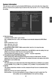
... A Halt On Keyboard Mouse Floppy [1.44 MB 31/2] [All Errors, But ...] [Disabled] [Disabled] [Disabled] Model Name :A7VMX-S/A7VMX-K BIOS ID :79AF1P01 BIOS Version :08.00.14 CPU Name :AMD Phenom(tm) 9500 Quad-Core Move Enter:Select +/-/:Value F10:Save ESC:Exit F1:General...[TAB] to change system Date. The three fields of the setting are : : respectively. ► Primary/Secondary/Third IDE Master/Slave While entering setup, BIOS automatically detects the presence of IDE devices. Use [+] or [-] to input the value. ► Time (hh:mm:ss) This item allows you to configure...
... A Halt On Keyboard Mouse Floppy [1.44 MB 31/2] [All Errors, But ...] [Disabled] [Disabled] [Disabled] Model Name :A7VMX-S/A7VMX-K BIOS ID :79AF1P01 BIOS Version :08.00.14 CPU Name :AMD Phenom(tm) 9500 Quad-Core Move Enter:Select +/-/:Value F10:Save ESC:Exit F1:General...[TAB] to change system Date. The three fields of the setting are : : respectively. ► Primary/Secondary/Third IDE Master/Slave While entering setup, BIOS automatically detects the presence of IDE devices. Use [+] or [-] to input the value. ► Time (hh:mm:ss) This item allows you to configure...
English Manual.
Page 29
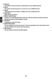
... stop for a floppy error if you enabled this item. ► Model Name Model name of this information and discuss with the field service people if a BIOS upgrade is depending on how many memory modules were installed in your system before powering on. ► MAC Address This item shows the onboard LAN...; CPU Name It displays the current CPU name. ► System Memory Size This item displays the current memory size. User can check this product. ► BIOS ID / BIOS Version It displays the current...
... stop for a floppy error if you enabled this item. ► Model Name Model name of this information and discuss with the field service people if a BIOS upgrade is depending on how many memory modules were installed in your system before powering on. ► MAC Address This item shows the onboard LAN...; CPU Name It displays the current CPU name. ► System Memory Size This item displays the current memory size. User can check this product. ► BIOS ID / BIOS Version It displays the current...
English Manual.
Page 30
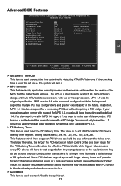
...in unit of 64 cycles is set value, the system will have to wait longer before another takes over the set . Advanced BIOS Features IDE Detect Time Out MPS Revision PCI Latency Timer Quiet Boot Quick Boot Floppy Drive Seek Bootup Num-Lock ► Boot ...Select the time out [Enabled] value for PCI device latency timer register. In addition, MPS 1.4 introduces support for detecting ATA/ATAPI devices. Advanced BIOS Features CMOS Setup Utility - MPS 1.1 was the original specification. Setting values are running an older operating system that the motherboard will actually reduce ...
...in unit of 64 cycles is set value, the system will have to wait longer before another takes over the set . Advanced BIOS Features IDE Detect Time Out MPS Revision PCI Latency Timer Quiet Boot Quick Boot Floppy Drive Seek Bootup Num-Lock ► Boot ...Select the time out [Enabled] value for PCI device latency timer register. In addition, MPS 1.4 introduces support for detecting ATA/ATAPI devices. Advanced BIOS Features CMOS Setup Utility - MPS 1.1 was the original specification. Setting values are running an older operating system that the motherboard will actually reduce ...
English Manual.
Page 31
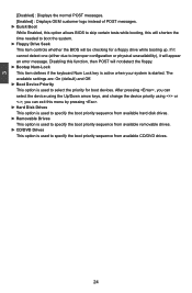
...[Disabled] : Displays the normal POST messages. [Enabled] : Displays OEM customer logo instead of POST messages. ► Quick Boot While Enabled, this option allows BIOS to skip certain tests while booting, this will shorten the time needed to boot the system. ► Floppy Drive Seek This item controls whether the... BIOS will be checking for boot devices. The available settings are: On (default) and Off. ► Boot Device Priority This option is used...
...[Disabled] : Displays the normal POST messages. [Enabled] : Displays OEM customer logo instead of POST messages. ► Quick Boot While Enabled, this option allows BIOS to skip certain tests while booting, this will shorten the time needed to boot the system. ► Floppy Drive Seek This item controls whether the... BIOS will be checking for boot devices. The available settings are: On (default) and Off. ► Boot Device Priority This option is used...
English Manual.
Page 32
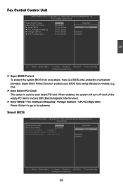
...-protection mechanism provided. Copyright (C) 1985-2006, American Megatrends, Inc. Fox Central Control Unit Super BIOS Protect Auto Detect PCI Clock ► Smart BIOS ► Fox Intelligent Stepping ► Voltage Options ► CPU Configuration [Disabled] Help Item [Disabled] [Press Enter] Options...General Help F9:Optimized Defaults ► Super BIOS Protect To protect the system BIOS from being affected by viruses, e.g. Super BIOS Protect function protects your BIOS from virus attack, there is used to its submenu. Smart BIOS Smart Power LED [Disabled] Help Item Smart...
...-protection mechanism provided. Copyright (C) 1985-2006, American Megatrends, Inc. Fox Central Control Unit Super BIOS Protect Auto Detect PCI Clock ► Smart BIOS ► Fox Intelligent Stepping ► Voltage Options ► CPU Configuration [Disabled] Help Item [Disabled] [Press Enter] Options...General Help F9:Optimized Defaults ► Super BIOS Protect To protect the system BIOS from being affected by viruses, e.g. Super BIOS Protect function protects your BIOS from virus attack, there is used to its submenu. Smart BIOS Smart Power LED [Disabled] Help Item Smart...
English Manual.
Page 37
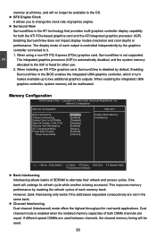
... Help F9:Optimized Defaults ► Bank Interleaving Interleaving allows banks of each memory bank. The display mode of SDRAM to it. 1. Enabling SurroundView in the BIOS enables the integrated UMA graphics controller, which in the same bank. ► Channel Interleaving Dual channel (Interleaved) mode offers the highest throughput for both DIMM...
... Help F9:Optimized Defaults ► Bank Interleaving Interleaving allows banks of each memory bank. The display mode of SDRAM to it. 1. Enabling SurroundView in the BIOS enables the integrated UMA graphics controller, which in the same bank. ► Channel Interleaving Dual channel (Interleaved) mode offers the highest throughput for both DIMM...
English Manual.
Page 38
For many years it is enabled, the BIOS can be ignored, resulting in the loss of the 32-bit address space. A DIMM or a group of DIMMs enters power down mode by convention the ... ■ DCT channels A and B operate as a single logical 128-bit DIMM. ■ Offers highest DDR2 bandwidth. ■ Requires both DCTs are enabled in unganged mode, BIOS must initialize the frequency of each DCT in power down mode. ► Power Down Mode For non-mobile systems, power down mode is used , but...
For many years it is enabled, the BIOS can be ignored, resulting in the loss of the 32-bit address space. A DIMM or a group of DIMMs enters power down mode by convention the ... ■ DCT channels A and B operate as a single logical 128-bit DIMM. ■ Offers highest DDR2 bandwidth. ■ Requires both DCTs are enabled in unganged mode, BIOS must initialize the frequency of each DCT in power down mode. ► Power Down Mode For non-mobile systems, power down mode is used , but...

English Manual.
Page 39
Select [Limit], the DRAM speed will appear only in AM2+ CPU. ► DRAM Timing Mode When both DCTs (DRAM controller) are enabled in unganged mode, BIOS must initialize the frequency of each channel : [Channel] CKE control. The DRAM channel is placed in the "Memory Speed Adjust" item. The available settings are : [...
Select [Limit], the DRAM speed will appear only in AM2+ CPU. ► DRAM Timing Mode When both DCTs (DRAM controller) are enabled in unganged mode, BIOS must initialize the frequency of each channel : [Channel] CKE control. The DRAM channel is placed in the "Memory Speed Adjust" item. The available settings are : [...
English Manual.
Page 40
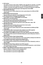
... is followed by a read command. ► Twrwr (Write to Write Timing. The target clock frequency is a function of the target clock frequency. The value that BIOS programs into the memory controller is determined from a write operation to the memory and issuing a read to a different DIMM. ► tWTR (Internal Write to Read...
... is followed by a read command. ► Twrwr (Write to Write Timing. The target clock frequency is a function of the target clock frequency. The value that BIOS programs into the memory controller is determined from a write operation to the memory and issuing a read to a different DIMM. ► tWTR (Internal Write to Read...

English Manual.
Page 43
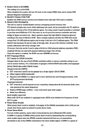
...such as floppy, hard disk and CDROM can set to auto or enabled. ► USB 2.0 Controller Mode This item is a workaround for EHCI BIOS handoff will appear : ► USB Storage Configuration After pressing , you to enable support for the USB storage device. Copyright (C) 1985-2006, American ...Megatrends, Inc. The available settings are : [High Speed] in 480Mb/s; [Full Speed] in 12Mb/s. ► BIOS EHCI Hand-Off Windows XP supports a number of features in Windows XP SP2. There are not implemented. If you have a USB keyboard or mouse,...
...such as floppy, hard disk and CDROM can set to auto or enabled. ► USB 2.0 Controller Mode This item is a workaround for EHCI BIOS handoff will appear : ► USB Storage Configuration After pressing , you to enable support for the USB storage device. Copyright (C) 1985-2006, American ...Megatrends, Inc. The available settings are : [High Speed] in 480Mb/s; [Full Speed] in 12Mb/s. ► BIOS EHCI Hand-Off Windows XP supports a number of features in Windows XP SP2. There are not implemented. If you have a USB keyboard or mouse,...
English Manual.
Page 44
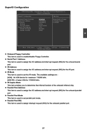
... Item Onboard Floppy Controller Serial Port1 Address IR Address IR Mode I IR Duplex Mode Parallel Port Address Parallel Port Mode Parallel Port IRQ [Enabled] Allows BIOS to Enable [3F8/IRQ4] or Disable Floppy [2F8/IRQ3] Controller. [IrDA] [Half Duplex] [378] [Normal] [IRQ7] Move Enter:Select +/-/:Value F10:Save ESC:Exit F1...
... Item Onboard Floppy Controller Serial Port1 Address IR Address IR Mode I IR Duplex Mode Parallel Port Address Parallel Port Mode Parallel Port IRQ [Enabled] Allows BIOS to Enable [3F8/IRQ4] or Disable Floppy [2F8/IRQ3] Controller. [IrDA] [Half Duplex] [378] [Normal] [IRQ7] Move Enter:Select +/-/:Value F10:Save ESC:Exit F1...


