English Manual.
Page 5
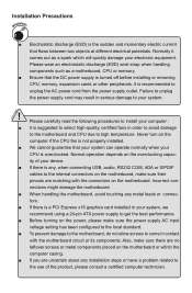
... is turned off before installing or removing CPU, memory, expansion cards or other peripherals. Failure to unplug the AC power cord from the power supply outlet. Please carefully read the following procedures to install your system, we recommend using a 24-pin ATX power supply to your electronic equipment. Incorrect con- CAUTION ■ Electrostatic discharge (ESD) is overclocked. Never turn on the motherboard. tors. ■ If there is a PCI Express x16 graphics card installed in...
... is turned off before installing or removing CPU, memory, expansion cards or other peripherals. Failure to unplug the AC power cord from the power supply outlet. Please carefully read the following procedures to install your system, we recommend using a 24-pin ATX power supply to your electronic equipment. Incorrect con- CAUTION ■ Electrostatic discharge (ESD) is overclocked. Never turn on the motherboard. tors. ■ If there is a PCI Express x16 graphics card installed in...
English Manual.
Page 9
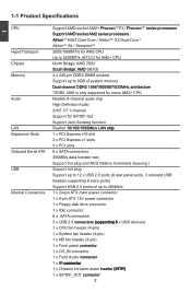
...;p�� Expansion Slots 1 x PCI Express x16 slot 2 x PCI Express x1 slots 3 x PCI slots Onboard Serial ATA 6 x SATA connectors 300MB/s data transfer rate Support hot plug and NCQ (Native Command Queuing ) USB Support hot plug Support up to 12 x USB 2.0 ports (6 rear panel ports, 3 onboard USB headers supporting 6 extra ports) Support USB 2.0 protocol up to 480Mb/s Internal Connectors 1 x 24-pin ATX main power connector 1 x 8-pin ATX 12V power connector 1 x Floppy disk drive connector 1 x IDE connector 6 x SATA connectors 3 x USB 2.0 c��...
...;p�� Expansion Slots 1 x PCI Express x16 slot 2 x PCI Express x1 slots 3 x PCI slots Onboard Serial ATA 6 x SATA connectors 300MB/s data transfer rate Support hot plug and NCQ (Native Command Queuing ) USB Support hot plug Support up to 12 x USB 2.0 ports (6 rear panel ports, 3 onboard USB headers supporting 6 extra ports) Support USB 2.0 protocol up to 480Mb/s Internal Connectors 1 x 24-pin ATX main power connector 1 x 8-pin ATX 12V power connector 1 x Floppy disk drive connector 1 x IDE connector 6 x SATA connectors 3 x USB 2.0 c��...
English Manual.
Page 14
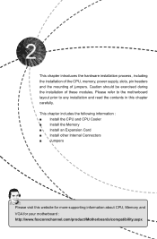
... CPU, Memory and VGA for your motherboard : http://www.foxconnchannel.com/product/Motherboards/compatibility.aspx This chapter introduces the hardware installation process, including the installation of the CPU, memory, power supply, slots, pin headers and the mounting of these modules. Caution should be exercised during the installation of jumpers. This chapter includes the following information : ■ Install the CPU and CPU Cooler ■ Install the Memory ■ Install an Expansion Card ■ Install other Internal Connectors ■ Jumpers...
... CPU, Memory and VGA for your motherboard : http://www.foxconnchannel.com/product/Motherboards/compatibility.aspx This chapter introduces the hardware installation process, including the installation of the CPU, memory, power supply, slots, pin headers and the mounting of these modules. Caution should be exercised during the installation of jumpers. This chapter includes the following information : ■ Install the CPU and CPU Cooler ■ Install the Memory ■ Install an Expansion Card ■ Install other Internal Connectors ■ Jumpers...

English Manual.
Page 19
... the PCI Express x16 slot. • Removing the Card: Push the latch at the end of the PCI Express x16 slot to make any required BIOS changes for your expansion card. ■ Always turn off the computer and unplug the power cord from the chassis back panel. 2. Carefully read the manual that supports your computer. Install the driver provided with the slot, and press down on your card. Installing and Removing a PCI Express x16 Graphics Card : • Installing a Graphics Card...
... the PCI Express x16 slot. • Removing the Card: Push the latch at the end of the PCI Express x16 slot to make any required BIOS changes for your expansion card. ■ Always turn off the computer and unplug the power cord from the chassis back panel. 2. Carefully read the manual that supports your computer. Install the driver provided with the slot, and press down on your card. Installing and Removing a PCI Express x16 Graphics Card : • Installing a Graphics Card...
English Manual.
Page 21
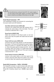
... are using a 4-pin power supply, you using the power supply button. This 2-pin connector is directional with +/- When the system is in S3/S4 sleep state or power off mode (S5), the LED is off rather than using an 8-pin ATX 12V power supply. Serial ATA Connectors : SATA_1/2/3/4/5/6 The Serial ATA connector is on the front panel of the chassis. 2 CAUTION Connect a 4-pin power plug ! This 2-pin connector is directional with SATA Hard Disk or CD devices which support this switch allows the system to the Reset switch on...
... are using a 4-pin power supply, you using the power supply button. This 2-pin connector is directional with +/- When the system is in S3/S4 sleep state or power off mode (S5), the LED is off rather than using an 8-pin ATX 12V power supply. Serial ATA Connectors : SATA_1/2/3/4/5/6 The Serial ATA connector is on the front panel of the chassis. 2 CAUTION Connect a 4-pin power plug ! This 2-pin connector is directional with SATA Hard Disk or CD devices which support this switch allows the system to the Reset switch on...
English Manual.
Page 24
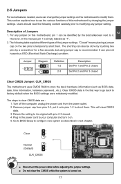
... modifying any jumper on this motherboard by changing the jumper settings. Clear CMOS data is recommended. Go to BIOS Setup to clear CMOS data are : 1. 2 2-5 Jumpers For some features needed, users can change the jumper settings on this manual, pin 1 is simply labeled as "1". 2. However, in next chapter. 1 Clear 2 3 WARNING! Jumper 1 Diagram 1 1 Definition 1-2 2-3 Description Set Pin 1 and Pin 2 closed Set Pin 2 and Pin 3 closed . 4. For any jumper setting. The following content carefully prior to modify them. The shorting can also...
... modifying any jumper on this motherboard by changing the jumper settings. Clear CMOS data is recommended. Go to BIOS Setup to clear CMOS data are : 1. 2 2-5 Jumpers For some features needed, users can change the jumper settings on this manual, pin 1 is simply labeled as "1". 2. However, in next chapter. 1 Clear 2 3 WARNING! Jumper 1 Diagram 1 1 Definition 1-2 2-3 Description Set Pin 1 and Pin 2 closed Set Pin 2 and Pin 3 closed . 4. For any jumper setting. The following content carefully prior to modify them. The shorting can also...

English Manual.
Page 27
... setup enables you to read/change anything and exit the setup. 20 If you set up through this menu to prevent unauthorized use of your CPU/System. ► BIOS Security Features The Supervisor/User password can be set a password, the system will ask you have more memory or I/O cards installed. However, it may offer better performance in correct password before boot or access to Setup. ► Load Optimal Defaults The optimal performance settings...
... setup enables you to read/change anything and exit the setup. 20 If you set up through this menu to prevent unauthorized use of your CPU/System. ► BIOS Security Features The Supervisor/User password can be set a password, the system will ask you have more memory or I/O cards installed. However, it may offer better performance in correct password before boot or access to Setup. ► Load Optimal Defaults The optimal performance settings...

English Manual.
Page 28
... While entering setup, BIOS automatically detects the presence of IDE devices. The halt condition can be enabled/disabled in system halt. Use [ENTER], [TAB] or [SHIFT-TAB] to configure the desired time. Year-year, set up by BIOS (Read Only). Use [+] or [-] to input the value. ► Time (hh:mm:ss) This item allows you enabled this message is automatically displayed by users. This item displays the drive...
... While entering setup, BIOS automatically detects the presence of IDE devices. The halt condition can be enabled/disabled in system halt. Use [ENTER], [TAB] or [SHIFT-TAB] to configure the desired time. Year-year, set up by BIOS (Read Only). Use [+] or [-] to input the value. ► Time (hh:mm:ss) This item allows you enabled this message is automatically displayed by users. This item displays the drive...
English Manual.
Page 29
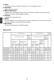
... IDE1 SATA 5 SATA 6 SATA 1 SATA 2 SATA as SATA as SATA as Primary SATA 5 SATA 6 SATA 1 SATA 2 SATA IDE Combined Mode Disabled SATA 1 SATA 2 OnChip SATA Channel Disabled SATA 5 SATA 6 - 3 ► Floppy The system boot will not stop for a floppy error if you enabled this item. ► Model Name Model name of this information and discuss with the field service people if a BIOS upgrade is depending on how many memory modules were installed in your system before powering on. ► MAC Address This item shows the onboard LAN...
... IDE1 SATA 5 SATA 6 SATA 1 SATA 2 SATA as SATA as SATA as Primary SATA 5 SATA 6 SATA 1 SATA 2 SATA IDE Combined Mode Disabled SATA 1 SATA 2 OnChip SATA Channel Disabled SATA 5 SATA 6 - 3 ► Floppy The system boot will not stop for a floppy error if you enabled this item. ► Model Name Model name of this information and discuss with the field service people if a BIOS upgrade is depending on how many memory modules were installed in your system before powering on. ► MAC Address This item shows the onboard LAN...

English Manual.
Page 34
... Clock Override [Enabled] GFX Engine Clock [350] Spread Spectrum [Enabled] � � Help Item 3 Move Enter:Select +/-/:Value F10:Save ESC:Exit F1:General Help F9:Optimized Defaults ► CPU Clock Adjust This option is used to adjust the CPU clock. ► PCIE Clock Adjust This option is set to enable/disable provision of PCI Express slot. This option will be displayed only if your CPU. Select [Limit], the DRAM speed will run at the specified "Memory Speed...
... Clock Override [Enabled] GFX Engine Clock [350] Spread Spectrum [Enabled] � � Help Item 3 Move Enter:Select +/-/:Value F10:Save ESC:Exit F1:General Help F9:Optimized Defaults ► CPU Clock Adjust This option is used to adjust the CPU clock. ► PCIE Clock Adjust This option is set to enable/disable provision of PCI Express slot. This option will be displayed only if your CPU. Select [Limit], the DRAM speed will run at the specified "Memory Speed...
English Manual.
Page 41
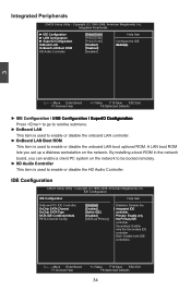
... Item U�S��B�C��o�n�f�ig�u�r�a�t�io�n� [Press Enter] ►���S��u�p�e�r�I �in the network board, you set up a diskless workstation on the network to be booted remotely. ► HD Audio Controller This item is used to enable or disable the onboard LAN boot optional ROM.
... Item U�S��B�C��o�n�f�ig�u�r�a�t�io�n� [Press Enter] ►���S��u�p�e�r�I �in the network board, you set up a diskless workstation on the network to be booted remotely. ► HD Audio Controller This item is used to enable or disable the onboard LAN boot optional ROM.
English Manual.
Page 42
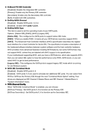
.... [Legacy IDE] - The specification includes a description of your SATA drives must also support AHCI. [AHCI] - If your motherboard supporting AHCI, and you have fair performance (only PATA, SATA level), or you enable RAID, it means all your SATA ports. When you can select IDE option to have a SATA device, which is running for Serial ATA. Four drives are used to set the operating mode of the hardware/software interface between system software and the host controller hardware. This configures...
.... [Legacy IDE] - The specification includes a description of your SATA drives must also support AHCI. [AHCI] - If your motherboard supporting AHCI, and you have fair performance (only PATA, SATA level), or you enable RAID, it means all your SATA ports. When you can select IDE option to have a SATA device, which is running for Serial ATA. Four drives are used to set the operating mode of the hardware/software interface between system software and the host controller hardware. This configures...
English Manual.
Page 43
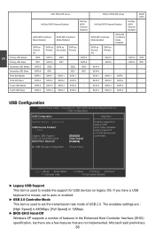
... IDE0 SATA as SATA as SATA as Primary SATA 5 SATA IDE Combined Mode Disabled - SATA 4 SATA 4 SATA 4 - - USB Configuration CMOS Setup Utility - If you have a USB keyboard or mouse, set to auto or enabled. ► USB 2.0 Controller Mode This item is used to enable the support for legacy USB. �U�S��B��D�e�v�i�c�e�s�E��n�a�b�le�d��: Auto option disables�� � 1 Drive legacy support if...
... IDE0 SATA as SATA as SATA as Primary SATA 5 SATA IDE Combined Mode Disabled - SATA 4 SATA 4 SATA 4 - - USB Configuration CMOS Setup Utility - If you have a USB keyboard or mouse, set to auto or enabled. ► USB 2.0 Controller Mode This item is used to enable the support for legacy USB. �U�S��B��D�e�v�i�c�e�s�E��n�a�b�le�d��: Auto option disables�� � 1 Drive legacy support if...
English Manual.
Page 47
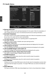
... supporting ACPI. ► Case Open Warning This item is used to enable or disable case open warning function. ► CPU/System Temperature The CPU/System temperature are automatically detected and displayed by the system. ► CPU Fan/System Fan Speed The CPU fan/System fan speed are automatically detected and displayed by the system. ► CPU Core/DRAM Voltage/+ 3.3V/+12.0V/+1.1V The current voltages are automatically detected and displayed by the system. ► CPU Smart Fan Function / System Smart Fan...
... supporting ACPI. ► Case Open Warning This item is used to enable or disable case open warning function. ► CPU/System Temperature The CPU/System temperature are automatically detected and displayed by the system. ► CPU Fan/System Fan Speed The CPU fan/System fan speed are automatically detected and displayed by the system. ► CPU Core/DRAM Voltage/+ 3.3V/+12.0V/+1.1V The current voltages are automatically detected and displayed by the system. ► CPU Smart Fan Function / System Smart Fan...

English Manual.
Page 51
... 9.0 F. AMD Chipset Driver B. FOX LiveUpdate C. AMD RAID Utility 44 Install Driver Use these options to install additional software programs. FOX ONE is set to install. 1. Adobe Acrobat Reader G. Software Utilities Use these options to install all the drivers have been installed. 4 Utility CD content This motherboard comes with one Utility CD. A. Realtek 811X LAN Driver D. You can simply put it into your CD/DVD-ROM drive, and the main menu will be displayed on your PC screen to guide you to BIOS. Realtek HDA Audio Driver C. FOX...
... 9.0 F. AMD Chipset Driver B. FOX LiveUpdate C. AMD RAID Utility 44 Install Driver Use these options to install additional software programs. FOX ONE is set to install. 1. Adobe Acrobat Reader G. Software Utilities Use these options to install all the drivers have been installed. 4 Utility CD content This motherboard comes with one Utility CD. A. Realtek 811X LAN Driver D. You can simply put it into your CD/DVD-ROM drive, and the main menu will be displayed on your PC screen to guide you to BIOS. Realtek HDA Audio Driver C. FOX...

English Manual.
Page 76
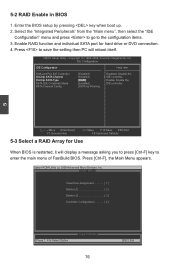
... SATA hard disks. 4. Creating a Non-Bootable Array - Existing Windows XP (or Vista) system with new RAID built as data storage. Several SATA hard disks. 3. Follow 5-3 to set RAID enabled in BIOS. 2. A RAID driver diskette. 5. Set RAID enabled in BIOS. 3. Follow 5-2 to select a RAID array for use . 4. Follow 5-3 to build a new RAID array in your current Windows XP system. 4. A CD/DVD-ROM drive. 2. Follow 5-5 to go through the processes to select a RAID array for use . 3. Follow 5-4 to create a RAID driver diskette. 2. A floppy drive. 2. A motherboard driver...
... SATA hard disks. 4. Creating a Non-Bootable Array - Existing Windows XP (or Vista) system with new RAID built as data storage. Several SATA hard disks. 3. Follow 5-3 to set RAID enabled in BIOS. 2. A RAID driver diskette. 5. Set RAID enabled in BIOS. 3. Follow 5-2 to select a RAID array for use . 4. Follow 5-3 to build a new RAID array in your current Windows XP system. 4. A CD/DVD-ROM drive. 2. Follow 5-5 to go through the processes to select a RAID array for use . 3. Follow 5-4 to create a RAID driver diskette. 2. A floppy drive. 2. A motherboard driver...
English Manual.
Page 83
... a RAID Array for hard drive or DVD connection. 4. Option ROM Utility (c) 2008 Advanced Micro Devices, Inc. [ Main Menu ] View Drive Assignment 1 ] Define LD 2 ] Delete LD 3 ] Controller Configuration 4 ] [ Keys Available ] Press 1..4 to the configuration items. 3. Enter the BIOS setup by pressing key when boot up. 2. IDE Configuration ��ID��E���C��o�n��fi�g�u��r�a�t�i�o�n� Help Item OnBoard PCI IDE...
... a RAID Array for hard drive or DVD connection. 4. Option ROM Utility (c) 2008 Advanced Micro Devices, Inc. [ Main Menu ] View Drive Assignment 1 ] Define LD 2 ] Delete LD 3 ] Controller Configuration 4 ] [ Keys Available ] Press 1..4 to the configuration items. 3. Enter the BIOS setup by pressing key when boot up. 2. IDE Configuration ��ID��E���C��o�n��fi�g�u��r�a�t�i�o�n� Help Item OnBoard PCI IDE...
English Manual.
Page 96
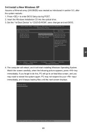
... will reboot, and it keeps loading files until the next screen displays. Press to "CD/DVD-ROM", save changes and exit BIOS. Watch the screen carefully, when the following picture appears, press key immediately. Set the "1st Boot Device" to enter BIOS Setup during POST. 2. The computer will go to an fatal blue screen, and you need to install a 3rd party SCSI or RAID driver. 89 PC may need to reboot...
... will reboot, and it keeps loading files until the next screen displays. Press to "CD/DVD-ROM", save changes and exit BIOS. Watch the screen carefully, when the following picture appears, press key immediately. Set the "1st Boot Device" to enter BIOS Setup during POST. 2. The computer will go to an fatal blue screen, and you need to install a 3rd party SCSI or RAID driver. 89 PC may need to reboot...

English Manual.
Page 97
... mass storage devices installed in your system, the following mass storage device(s): * To specify additional SCSI adapters, CD-ROM drivers, or special disk controllers for use with Windows, including those for the following picture appears, press to insert the RAID driver diskette into Drive A: * Press ENTER when ready Enter=Continue ESC=Cancel F3=Exit 90 Currently, Setup will ask you floppy drive. Windows Setup Please insert the disk labeled manufacturer-supplied hardware support disk into...
... mass storage devices installed in your system, the following mass storage device(s): * To specify additional SCSI adapters, CD-ROM drivers, or special disk controllers for use with Windows, including those for the following picture appears, press to insert the RAID driver diskette into Drive A: * Press ENTER when ready Enter=Continue ESC=Cancel F3=Exit 90 Currently, Setup will ask you floppy drive. Windows Setup Please insert the disk labeled manufacturer-supplied hardware support disk into...
English Manual.
Page 100
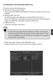
... SATA Type [RAID] Enable: Enable the SATA IDE Combined Mode [Enabled] IDE controller. PATA Channel Config [SATA as a mirrored RAID1 array, they are : Hitachi HDT725025VLA3, (250.05GB) connected to SATA port2 of the motherboard. Though we highly recommend you using different brand of hard disks as an example here, the purpose is connected to the IDE channel, and set to "IDE Configuration" menu. 5 5-5 Setting Up a Non-Bootable RAID Array This section assumes the following setup : ■ Boot Disk with the same brand, size and model...
... SATA Type [RAID] Enable: Enable the SATA IDE Combined Mode [Enabled] IDE controller. PATA Channel Config [SATA as a mirrored RAID1 array, they are : Hitachi HDT725025VLA3, (250.05GB) connected to SATA port2 of the motherboard. Though we highly recommend you using different brand of hard disks as an example here, the purpose is connected to the IDE channel, and set to "IDE Configuration" menu. 5 5-5 Setting Up a Non-Bootable RAID Array This section assumes the following setup : ■ Boot Disk with the same brand, size and model...


