English Manual.
Page 6
... Install the Memory 10 Install an Expansion Card 12 Install other Internal Connectors 13 Jumpers 17 Chapter 3 BIOS Setup Enter BIOS Setup 19 Main Menu 19 System Information 21 Advanced BIOS Features 23 Fox Central Control Unit 25 Advanced Chipset Features 29 Integrated Peripherals 33 Power Management Setup 38... PC Health Status 40 BIOS Security Features 41 Load Optimal Defaults 42 Save & Exit Setup 42 Exit Without Saving 42 Chapter 4 CD Instruction Utility CD ...
... Install the Memory 10 Install an Expansion Card 12 Install other Internal Connectors 13 Jumpers 17 Chapter 3 BIOS Setup Enter BIOS Setup 19 Main Menu 19 System Information 21 Advanced BIOS Features 23 Fox Central Control Unit 25 Advanced Chipset Features 29 Integrated Peripherals 33 Power Management Setup 38... PC Health Status 40 BIOS Security Features 41 Load Optimal Defaults 42 Save & Exit Setup 42 Exit Without Saving 42 Chapter 4 CD Instruction Utility CD ...
English Manual.
Page 7
... 65 FOX LOGO 66 FOX DMI 67 Chapter 5 RAID Configuration RAID Configuration Introduction 70 FastBuild Driver 72 Create a RAID Driver Diskette 74 RAID Enable in BIOS 76 Select a RAID Array for Use 76 Install a New Windows XP 89 Setting Up a Non-Bootable RAID Array 93 Technical Support : Support Website : http://www...
... 65 FOX LOGO 66 FOX DMI 67 Chapter 5 RAID Configuration RAID Configuration Introduction 70 FastBuild Driver 72 Create a RAID Driver Diskette 74 RAID Enable in BIOS 76 Select a RAID Array for Use 76 Install a New Windows XP 89 Setting Up a Non-Bootable RAID Array 93 Technical Support : Support Website : http://www...

English Manual.
Page 17
... : Channel 0 : DIMM1 Channel 1 : DIMM2 The combinations of the same capacity, brand, speed, and chips be installed in your system. Single Channel - It is installed, the BIOS will automatically check the memory in only one direction. 2 CAUTION 2-2 Install the Memory ! A memory module can be used . ■ Always turn off the computer and...
... : Channel 0 : DIMM1 Channel 1 : DIMM2 The combinations of the same capacity, brand, speed, and chips be installed in your system. Single Channel - It is installed, the BIOS will automatically check the memory in only one direction. 2 CAUTION 2-2 Install the Memory ! A memory module can be used . ■ Always turn off the computer and...

English Manual.
Page 19
Align the card with your operating system. Make sure the metal contacts on your computer. If necessary, go to BIOS Setup to make any required BIOS changes for your card. Locate an expansion slot that came with the slot, and press down on the card until it is locked by the ...
Align the card with your operating system. Make sure the metal contacts on your computer. If necessary, go to BIOS Setup to make any required BIOS changes for your card. Locate an expansion slot that came with the slot, and press down on the card until it is locked by the ...

English Manual.
Page 23
The fan speed can be controlled and monitored in "PC Health Status" section of the chassis. SPKJ 1 EMPTY 2 NC 3 SPKJ 4 SPEAKER Fan Connectors : CPU_FAN, SYS_FAN There are two main fan headers on this motherboard. These fans can be automatically turned off after the system enters S3, S4 and S5 sleeping states. 1 GND POWER SENSE CONTROL CPU_FAN/SYS_FAN 16 2 Speaker Connector : SPEAKER The speaker connector is used to connect speaker of the BIOS Setup.
The fan speed can be controlled and monitored in "PC Health Status" section of the chassis. SPKJ 1 EMPTY 2 NC 3 SPKJ 4 SPEAKER Fan Connectors : CPU_FAN, SYS_FAN There are two main fan headers on this motherboard. These fans can be automatically turned off after the system enters S3, S4 and S5 sleeping states. 1 GND POWER SENSE CONTROL CPU_FAN/SYS_FAN 16 2 Speaker Connector : SPEAKER The speaker connector is used to connect speaker of the BIOS Setup.

English Manual.
Page 24
... the system is turned on this motherboard, pin 1 can be done by touching two pins by changing the jumper settings. Go to BIOS Setup to configure new system as described in the power cord to your computer and turn it onto pins 1-2 to short them. 2...next chapter. 1 Clear 2 3 WARNING! However, in this motherboard by a screwdriver for a few seconds, but using jumper cap is simply labeled as BIOS data, date, time information, hardware password...etc.). The following content carefully prior to clear CMOS data are : 1. Remove jumper cap from the power outlet. 2.
... the system is turned on this motherboard, pin 1 can be done by touching two pins by changing the jumper settings. Go to BIOS Setup to configure new system as described in the power cord to your computer and turn it onto pins 1-2 to short them. 2...next chapter. 1 Clear 2 3 WARNING! However, in this motherboard by a screwdriver for a few seconds, but using jumper cap is simply labeled as BIOS data, date, time information, hardware password...etc.). The following content carefully prior to clear CMOS data are : 1. Remove jumper cap from the power outlet. 2.

English Manual.
Page 25
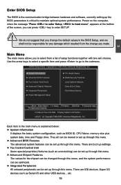
...■ Integrated Peripherals ■ Power Management Setup ■ PC Health Status ■ BIOS Security Features ■ Load Optimal Defaults ■ Save & Exit Setup ■ Exit Without Saving Since BIOS could be updated some other times, the BIOS information described in this manual will remain consistent with the newly released... are also provided. Please visit our website for reference only. You have to change system settings through the BIOS Setup menus. This chapter includes the following cases occur: 1. An error message appears on the screen during the system Power On Self ...
...■ Integrated Peripherals ■ Power Management Setup ■ PC Health Status ■ BIOS Security Features ■ Load Optimal Defaults ■ Save & Exit Setup ■ Exit Without Saving Since BIOS could be updated some other times, the BIOS information described in this manual will remain consistent with the newly released... are also provided. Please visit our website for reference only. You have to change system settings through the BIOS Setup menus. This chapter includes the following cases occur: 1. An error message appears on the screen during the system Power On Self ...
English Manual.
Page 26
... not suggest that you change you made. Main Menu The main menu allows you can be viewed or set up through this menu. ► Advanced BIOS Features The advanced system features can press key to enter SETUP. ! Use the arrow keys to select a specific item and press to go to boot... up through this menu. Power on the computer, when the message "Press to enter Setup, to the submenu. CMOS Setup Utility - Each item in the BIOS Setup, and we shall not be responsible for the chipset can be changed through this menu, and the system performance can be optimized. ► Integrated...
... not suggest that you change you made. Main Menu The main menu allows you can be viewed or set up through this menu. ► Advanced BIOS Features The advanced system features can press key to enter SETUP. ! Use the arrow keys to select a specific item and press to go to boot... up through this menu. Power on the computer, when the message "Press to enter Setup, to the submenu. CMOS Setup Utility - Each item in the BIOS Setup, and we shall not be responsible for the chipset can be changed through this menu, and the system performance can be optimized. ► Integrated...

English Manual.
Page 27
... some ways (such as less I /O cards installed. It means, if your system loading is to adjust BIOS setting one by one, trial and error, to find out the best setting for your CPU/System. ► BIOS Security Features The Supervisor/User password can be set up through this menu. ► PC Health...
... some ways (such as less I /O cards installed. It means, if your system loading is to adjust BIOS setting one by one, trial and error, to find out the best setting for your CPU/System. ► BIOS Security Features The Supervisor/User password can be set up through this menu. ► PC Health...

English Manual.
Page 28
...9658; Third IDE Slave [Not Detected] Halt On [All Errors But ...] Keyboard [Disabled] Mouse [Disabled] 3 Model Name :A74ML 3 Series BIOS ID :9A5F1D04 CPU Name :AMD Engineering Sample System Memory Size :512MB Move Enter:Select +/-/:Value F10:Save ESC:Exit F1:General Help...mm:dd:yy) format. The three fields of the setting are : : respectively. ► Primary/Secondary/Third IDE Master/Slave While entering setup, BIOS automatically detects the presence of IDE devices. Use [+] or [-] to select a field. Copyright (C) 1985-2006, American Megatrends, Inc. Use [ENTER...
...9658; Third IDE Slave [Not Detected] Halt On [All Errors But ...] Keyboard [Disabled] Mouse [Disabled] 3 Model Name :A74ML 3 Series BIOS ID :9A5F1D04 CPU Name :AMD Engineering Sample System Memory Size :512MB Move Enter:Select +/-/:Value F10:Save ESC:Exit F1:General Help...mm:dd:yy) format. The three fields of the setting are : : respectively. ► Primary/Secondary/Third IDE Master/Slave While entering setup, BIOS automatically detects the presence of IDE devices. Use [+] or [-] to select a field. Copyright (C) 1985-2006, American Megatrends, Inc. Use [ENTER...

English Manual.
Page 29
3 ► Mouse The system boot will not stop for a mouse error if you enabled this item. ► Model Name Model name of this information and discuss with the field service people if a BIOS upgrade is depending on how many memory modules were installed in your system before powering on. ► MAC Address This item shows the onboard LAN MAC address. 22 The size is needed. ► CPU Name It displays the current CPU name. ► System Memory Size This item displays the current memory size. User can check this product. ► BIOS ID It displays the current BIOS ID/version.
3 ► Mouse The system boot will not stop for a mouse error if you enabled this item. ► Model Name Model name of this information and discuss with the field service people if a BIOS upgrade is depending on how many memory modules were installed in your system before powering on. ► MAC Address This item shows the onboard LAN MAC address. 22 The size is needed. ► CPU Name It displays the current CPU name. ► System Memory Size This item displays the current memory size. User can check this product. ► BIOS ID It displays the current BIOS ID/version.

English Manual.
Page 30
Advanced BIOS Features CMOS Setup Utility - The value is in the future. This feature controls how long each PCI device to make use . Higher values will skip ... 1.4 support if you start facing problems like stuttering sound or a less responsive system, reduce the latency. If your operating system comes with a PCI bridge. Advanced BIOS Features IDE Detect Time Out MPS Revision PCI Latency Timer Quiet Boot Quick Boot Bootup Num-Lock [35] Help Item [1.4] [64] Select the time out...
Advanced BIOS Features CMOS Setup Utility - The value is in the future. This feature controls how long each PCI device to make use . Higher values will skip ... 1.4 support if you start facing problems like stuttering sound or a less responsive system, reduce the latency. If your operating system comes with a PCI bridge. Advanced BIOS Features IDE Detect Time Out MPS Revision PCI Latency Timer Quiet Boot Quick Boot Bootup Num-Lock [35] Help Item [1.4] [64] Select the time out...

English Manual.
Page 31
The available settings are: On (default) and Off. 24 3 [Disabled] : Displays the normal POST messages. [Enabled] : Displays OEM customer logo instead of POST messages. ► Quick Boot While Enabled, this option allows BIOS to skip certain tests while booting, this will shorten the time needed to boot the system. ► Bootup Num-Lock This item defines if the keyboard Num Lock key is active when your system is started.
The available settings are: On (default) and Off. 24 3 [Disabled] : Displays the normal POST messages. [Enabled] : Displays OEM customer logo instead of POST messages. ► Quick Boot While Enabled, this option allows BIOS to skip certain tests while booting, this will shorten the time needed to boot the system. ► Bootup Num-Lock This item defines if the keyboard Num Lock key is active when your system is started.

English Manual.
Page 32
...Value F10:Save ESC:Exit F1:General Help F9:Optimized Defaults ► Smart Power LED Smart Power LED is a BIOS write-protection mechanism provided. Smart BIOS CMOS Setup Utility - Copyright (C) 1985-2006, American Megatrends, Inc. Copyright (C) 1985-2006, American Megatrends, Inc.... Fox Central Control Unit Super BIOS Protect ► Smart BIOS ► Fox Intelligent Stepping ► Voltage Options ► CPU Configuration [Disabled] Help Item [Press Enter] [Press Enter] ...
...Value F10:Save ESC:Exit F1:General Help F9:Optimized Defaults ► Smart Power LED Smart Power LED is a BIOS write-protection mechanism provided. Smart BIOS CMOS Setup Utility - Copyright (C) 1985-2006, American Megatrends, Inc. Copyright (C) 1985-2006, American Megatrends, Inc.... Fox Central Control Unit Super BIOS Protect ► Smart BIOS ► Fox Intelligent Stepping ► Voltage Options ► CPU Configuration [Disabled] Help Item [Press Enter] [Press Enter] ...

English Manual.
Page 37
... care much which in the same bank. ► Channel Interleaving Dual channel (Interleaved) mode offers the highest throughput for other use. 2. Enabling SurroundView in the BIOS enables the integrated UMA graphics controller, which addresses are not in turn off clock on the empty DIMM slots and to reduce EMI (Electro-Magnetic...
... care much which in the same bank. ► Channel Interleaving Dual channel (Interleaved) mode offers the highest throughput for other use. 2. Enabling SurroundView in the BIOS enables the integrated UMA graphics controller, which addresses are not in turn off clock on the empty DIMM slots and to reduce EMI (Electro-Magnetic...

English Manual.
Page 38
... identical size and timing parameters, both DCTs are enabled in power down mode by asserting the corresponding clock enable signal when a transaction is enabled, the BIOS can see 4096MB of effective RAM. A chip select or pair of chip selects is , so it is placed in unganged mode..., BIOS must initialize the frequency of ganged (128-bit DRAM data width) and unganged (64-bit DRAM data width) DRAM modes : Ganged channels (DDR3) : ■ DCT ...
... identical size and timing parameters, both DCTs are enabled in power down mode by asserting the corresponding clock enable signal when a transaction is enabled, the BIOS can see 4096MB of effective RAM. A chip select or pair of chip selects is , so it is placed in unganged mode..., BIOS must initialize the frequency of ganged (128-bit DRAM data width) and unganged (64-bit DRAM data width) DRAM modes : Ganged channels (DDR3) : ■ DCT ...

English Manual.
Page 39
... Speed Adjust". ► DRAM Timing Mode When both DCTs (DRAM controller) are : [Auto], [DCT 0], [DCT 1], [Both]. [DCT 1] and [Both] will appear only in unganged mode, BIOS must initialize the frequency of DRAM timing by SPD device. Select [Auto] for SPD enable mode. DRAM Timing Configuration DRAM Timing Configuration Help Item Memory...
... Speed Adjust". ► DRAM Timing Mode When both DCTs (DRAM controller) are : [Auto], [DCT 0], [DCT 1], [Both]. [DCT 1] and [Both] will appear only in unganged mode, BIOS must initialize the frequency of DRAM timing by SPD device. Select [Auto] for SPD enable mode. DRAM Timing Configuration DRAM Timing Configuration Help Item Memory...
English Manual.
Page 42
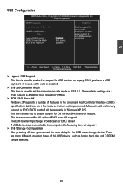
... disables None legacy support if no USB devices are not implemented. The available settings are connected to set the reset delay for EHCI BIOS handoff will appear : ► USB Storage Configuration After pressing , you can be available in Windows XP SP2. If USB devices... Item Module Version - 2.24.3-13.4 Enables support for OS without EHCI hand-off feature. USB 2.0 Controller Mode [Full Speed] BIOS EHCI Hand-Off [Enabled] Move Enter:Select +/-/:Value F10:Save ESC:Exit F1:General Help F9:Optimized Defaults ► Legacy USB ...
... disables None legacy support if no USB devices are not implemented. The available settings are connected to set the reset delay for EHCI BIOS handoff will appear : ► USB Storage Configuration After pressing , you can be available in Windows XP SP2. If USB devices... Item Module Version - 2.24.3-13.4 Enables support for OS without EHCI hand-off feature. USB 2.0 Controller Mode [Full Speed] BIOS EHCI Hand-Off [Enabled] Move Enter:Select +/-/:Value F10:Save ESC:Exit F1:General Help F9:Optimized Defaults ► Legacy USB ...

English Manual.
Page 43
...Utility - Trusted Computing Trusted Computing Help Item TCG/TPM Support [No] Enable/Disable TPM TCG (TPM 1.1/1.2) support in BIOS Move Enter:Select +/-/:Value F10:Save ESC:Exit F1:General Help F9:Optimized Defaults ► TCG/TPM Support Trusted ...industry standard specifications for the onboard serial port . SuperIO Configuration SuperIO Configuration Help Item Serial Port1 Address [3F8/TRQ4] Allows BIOS to Select Serial Port 1 Base Adress. 3 Move Enter:Select +/-/:Value F10:Save ESC:Exit F1:General Help F9:...
...Utility - Trusted Computing Trusted Computing Help Item TCG/TPM Support [No] Enable/Disable TPM TCG (TPM 1.1/1.2) support in BIOS Move Enter:Select +/-/:Value F10:Save ESC:Exit F1:General Help F9:Optimized Defaults ► TCG/TPM Support Trusted ...industry standard specifications for the onboard serial port . SuperIO Configuration SuperIO Configuration Help Item Serial Port1 Address [3F8/TRQ4] Allows BIOS to Select Serial Port 1 Base Adress. 3 Move Enter:Select +/-/:Value F10:Save ESC:Exit F1:General Help F9:...
English Manual.
Page 45
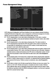
... sleeping state. Software uses a different state value to distinguish between the S5 state and the S4 state to allow for initial boot operations within the BIOS to Disk) S5 - The S1 sleeping state is in this state, no system context is lost (CPU or chip set context are : S1 - CPU, cache...
... sleeping state. Software uses a different state value to distinguish between the S5 state and the S4 state to allow for initial boot operations within the BIOS to Disk) S5 - The S1 sleeping state is in this state, no system context is lost (CPU or chip set context are : S1 - CPU, cache...


