User Manual
Page 1
All rights reserved. Specifications subject to change without notice. All product names are trademarks of their respective companies. ® TiR2,TiR3,TiR4, Ti40,Ti45,Ti50,Ti55 IR FlexCam Thermal Imagers Users Manual January 2007, Rev.2, 5/09 ©2007, 2009 Fluke Corporation.
All rights reserved. Specifications subject to change without notice. All product names are trademarks of their respective companies. ® TiR2,TiR3,TiR4, Ti40,Ti45,Ti50,Ti55 IR FlexCam Thermal Imagers Users Manual January 2007, Rev.2, 5/09 ©2007, 2009 Fluke Corporation.

User Manual
Page 3
Table of Contents Chapter Title Page 1 Introduction 1-1 Introduction 1-1 Contacting Fluke 1-2 Safety Information 1-2 Standard Accessories 1-4 Charge and Insert Battery 1-6 Power Camera On 1-7 Insert Memory Card 1-8 Focus...1-8 Set Temperature Level and Span 1-9 Set IR-Fusion® Blend Level 1-9 Capturing an Image 1-10 SmartView Software for Your PC 1-11 2 Camera Overview 2-1 Introduction 2-1 Camera Parts 2-2 Camera Display...
Table of Contents Chapter Title Page 1 Introduction 1-1 Introduction 1-1 Contacting Fluke 1-2 Safety Information 1-2 Standard Accessories 1-4 Charge and Insert Battery 1-6 Power Camera On 1-7 Insert Memory Card 1-8 Focus...1-8 Set Temperature Level and Span 1-9 Set IR-Fusion® Blend Level 1-9 Capturing an Image 1-10 SmartView Software for Your PC 1-11 2 Camera Overview 2-1 Introduction 2-1 Camera Parts 2-2 Camera Display...

User Manual
Page 4
...Annotations Lists in SmartView 4-12 5 Visible Light Camera Module (VLCM 5-1 Enabling/Disabling Visible Light Camera Module 5-1 Using Image Alignment 5-1 Focusing 5-2 Adjusting IR-VL IR-Fusion® Blend Level 5-3 Using Full Screen or Picture-in-Picture View 5-4 Adjusting Brightness and Color Controls 5-4 Using Torch Control 5-5 Using Visible ... Enhancing the Image 7-1 Using Auto Capture 7-1 Using User-Defined Display Screen Temperature Markers 7-4 Using Internal Recalibration 7-7 8 Camera Care 8-1 Cleaning the IR Lens, VLCM, Display Screen, and Body 8-1 Using Other Lenses 8-2 ii
...Annotations Lists in SmartView 4-12 5 Visible Light Camera Module (VLCM 5-1 Enabling/Disabling Visible Light Camera Module 5-1 Using Image Alignment 5-1 Focusing 5-2 Adjusting IR-VL IR-Fusion® Blend Level 5-3 Using Full Screen or Picture-in-Picture View 5-4 Adjusting Brightness and Color Controls 5-4 Using Torch Control 5-5 Using Visible ... Enhancing the Image 7-1 Using Auto Capture 7-1 Using User-Defined Display Screen Temperature Markers 7-4 Using Internal Recalibration 7-7 8 Camera Care 8-1 Cleaning the IR Lens, VLCM, Display Screen, and Body 8-1 Using Other Lenses 8-2 ii

User Manual
Page 9
...--Example 3 2-7 2-7. Standard Accessories 1-5 1-2. Camera Display Screen--Example 2 2-7 2-6. List of Figures Figure Title Page 1-1. Camera Back View 2-3 2-2. Focusing the Camera 1-8 1-6. Aligning the 20-mm Lens 5-2 vii Inserting a Memory Card 1-8 1-5. Turning the Power On and Off 1-7 1-4. Setting the IR-Fusion® Blend Level 1-10 1-8. Capturing an Image 1-11 2-1. Inserting and Removing a Memory Card 2-13 5-1.
...--Example 3 2-7 2-7. Standard Accessories 1-5 1-2. Camera Display Screen--Example 2 2-7 2-6. List of Figures Figure Title Page 1-1. Camera Back View 2-3 2-2. Focusing the Camera 1-8 1-6. Aligning the 20-mm Lens 5-2 vii Inserting a Memory Card 1-8 1-5. Turning the Power On and Off 1-7 1-4. Setting the IR-Fusion® Blend Level 1-10 1-8. Capturing an Image 1-11 2-1. Inserting and Removing a Memory Card 2-13 5-1.

User Manual
Page 11
...-radiometric solutions available. The TIR3, TiR4, Ti50 and Ti55 cameras use a detector with 160 x 120 resolution. The unique control image and IR-Fusion® technology enables you for specific features available on your camera. This is minimal and the infrared image appears to hereafter as the ... infrared camera (referred to be all one color. Refer to manage and analyze images captured with 320 x 240 resolution. The IR FlexCam is available in low contrast scenes where the temperature differential is especially helpful in 7models. Building Science • Roofing-Detect ...
...-radiometric solutions available. The TIR3, TiR4, Ti50 and Ti55 cameras use a detector with 160 x 120 resolution. The unique control image and IR-Fusion® technology enables you for specific features available on your camera. This is minimal and the infrared image appears to hereafter as the ... infrared camera (referred to be all one color. Refer to manage and analyze images captured with 320 x 240 resolution. The IR FlexCam is available in low contrast scenes where the temperature differential is especially helpful in 7models. Building Science • Roofing-Detect ...

User Manual
Page 13
...permanent loss of precision equipment. • Your infrared camera is a precision instrument that uses a sensitive infrared (IR) detector. We recommend that emit laser radiation and reflections from these devices-may adversely affect camera accuracy and may ...exposure. • Do not use camera in a manner not specified in Appendix B for certification. Pointing your camera's IR detector. • Your camera was calibrated prior to warm up before accurate measurements are available. *W Warning •...you would any type of data. Contact Fluke for proper calibration every two years.
...permanent loss of precision equipment. • Your infrared camera is a precision instrument that uses a sensitive infrared (IR) detector. We recommend that emit laser radiation and reflections from these devices-may adversely affect camera accuracy and may ...exposure. • Do not use camera in a manner not specified in Appendix B for certification. Pointing your camera's IR detector. • Your camera was calibrated prior to warm up before accurate measurements are available. *W Warning •...you would any type of data. Contact Fluke for proper calibration every two years.

User Manual
Page 19
... dialog box to automatically set the camera's temperature level and span. 2. Tap the trigger button ( ) to properly scale the image. Press and hold G until the IR-Fusion® blend level dialog box appears on the display screen. 2. Setting the Level and Span eii006.eps Set... IR-Fusion® Blend Level Note IR-Fusion® blending is disabled with optional 10 and 54-mm lenses. 1. Press G as needed to retain settings. 1-9 While continuing to press G, use the mouse ...
... dialog box to automatically set the camera's temperature level and span. 2. Tap the trigger button ( ) to properly scale the image. Press and hold G until the IR-Fusion® blend level dialog box appears on the display screen. 2. Setting the Level and Span eii006.eps Set... IR-Fusion® Blend Level Note IR-Fusion® blending is disabled with optional 10 and 54-mm lenses. 1. Press G as needed to retain settings. 1-9 While continuing to press G, use the mouse ...

User Manual
Page 20
... store images. 4. Review the image and camera settings. 3. Note The memory card must be inserted into the camera to pause the live image. 2. Setting the IR-Fusion® Blend Level eii007.eps Capturing an Image 1. Tap once (shown in the upper left-hand corner of the display screen indicating the image...
... store images. 4. Review the image and camera settings. 3. Note The memory card must be inserted into the camera to pause the live image. 2. Setting the IR-Fusion® Blend Level eii007.eps Capturing an Image 1. Tap once (shown in the upper left-hand corner of the display screen indicating the image...

User Manual
Page 26
C F Menu button - Can be programmed to D perform different menu functions, see Programming Function Buttons later in current image and to adjust IR IR-Fusion® level. Solid green = power is on or off and G to DC power adapter. Used to access display screen menus. K Liquid Crystal Display (LCD) ...
C F Menu button - Can be programmed to D perform different menu functions, see Programming Function Buttons later in current image and to adjust IR IR-Fusion® level. Solid green = power is on or off and G to DC power adapter. Used to access display screen menus. K Liquid Crystal Display (LCD) ...

User Manual
Page 31
... and location of marker point in -picture (PIP) - You can add up to full visible light (VL) or some combination in the box (when enabled). IR-Fusion® blend level dialog box - 2 Camera Overview Camera Display Screen Table 2-2. R Analysis area - Descriptions (cont.) Item Description Center box with the N maximum, average, .... Temperature of the coldest temperature in blue (when enabled). Disabled when using optional 10 and 54-mm lenses. 2-9 Display Screen - Used to change the IR-Fusion® T blend level from full infrared (IR) to three marker areas (when enabled).
... and location of marker point in -picture (PIP) - You can add up to full visible light (VL) or some combination in the box (when enabled). IR-Fusion® blend level dialog box - 2 Camera Overview Camera Display Screen Table 2-2. R Analysis area - Descriptions (cont.) Item Description Center box with the N maximum, average, .... Temperature of the coldest temperature in blue (when enabled). Disabled when using optional 10 and 54-mm lenses. 2-9 Display Screen - Used to change the IR-Fusion® T blend level from full infrared (IR) to three marker areas (when enabled).

User Manual
Page 54
...image only; Focus by aligning the edges of the IR and VL images. 5-2 Aligning the 20-mm Lens eii021.eps Focusing Prior to capturing images using the visible light module and IR-Fusion®, it is in focus and stop rotating the IR lens, the IR-Fusion® level returns to your finger. As you... have the target object in focus. To focus the camera, remove the IR lens...
...image only; Focus by aligning the edges of the IR and VL images. 5-2 Aligning the 20-mm Lens eii021.eps Focusing Prior to capturing images using the visible light module and IR-Fusion®, it is in focus and stop rotating the IR lens, the IR-Fusion® level returns to your finger. As you... have the target object in focus. To focus the camera, remove the IR lens...

User Manual
Page 55
... popup menu and tap E. 3. Tap to accept setting change and return to position the pointer over the VLCM tab and tap E. To adjust the IR-VL Fusion blend level using the level & span button and mouse controller: 1. Use the mouse controller to scan target mode. Position the pointer over ...Camera Settings on the tab bar and tap E to scroll to scan target mode. 5-3 5 Visible Light Camera Module (VLCM) Adjusting IR-VL IR-Fusion® Blend Level Adjusting IR-VL IR-Fusion® Blend Level Note This feature is VL. Tap to accept setting change and return to the VLCM tab. 4. To adjust...
... popup menu and tap E. 3. Tap to accept setting change and return to position the pointer over the VLCM tab and tap E. To adjust the IR-VL Fusion blend level using the level & span button and mouse controller: 1. Use the mouse controller to scan target mode. Position the pointer over ...Camera Settings on the tab bar and tap E to scroll to scan target mode. 5-3 5 Visible Light Camera Module (VLCM) Adjusting IR-VL IR-Fusion® Blend Level Adjusting IR-VL IR-Fusion® Blend Level Note This feature is VL. Tap to accept setting change and return to the VLCM tab. 4. To adjust...

User Manual
Page 56
...Tap to accept setting change and return to a programmable button (see Chapter 2). To enable high brightness and/or vivid color: 5-4 If the IR-Fusion® blend setting is Full Visible, then the visible light (VL) image is displayed. Adjusting Brightness and Color Controls Use the brightness and...button as needed. Tap F. 2. Then, to fit inside the visible light picture (picture-inpicture). For example, if the IR-Fusion® blend setting is Full IR, then the infrared image is displayed. Position the pointer over Camera Settings on all areas of view, thus enabling the infrared ...
...Tap to accept setting change and return to a programmable button (see Chapter 2). To enable high brightness and/or vivid color: 5-4 If the IR-Fusion® blend setting is Full Visible, then the visible light (VL) image is displayed. Adjusting Brightness and Color Controls Use the brightness and...button as needed. Tap F. 2. Then, to fit inside the visible light picture (picture-inpicture). For example, if the IR-Fusion® blend setting is Full IR, then the infrared image is displayed. Position the pointer over Camera Settings on all areas of view, thus enabling the infrared ...

User Manual
Page 58
... can also be enabled to the VLCM tab. 4. Position the pointer over the VLCM tab and tap E. You can view the images using the Full IR or Full Visible settings or blended in this function enabled, both the visible light and the infrared images are enabled, the torch operates continuously, while...
... can also be enabled to the VLCM tab. 4. Position the pointer over the VLCM tab and tap E. You can view the images using the Full IR or Full Visible settings or blended in this function enabled, both the visible light and the infrared images are enabled, the torch operates continuously, while...

User Manual
Page 59
Tap to a programmable button (see Chapter 2). Using appropriate IR-Fusion® blend levels and color palette settings allows the red laser dot to switch between IRonly, fused, and VL-only image thumbnail displays. Assign ...
Tap to a programmable button (see Chapter 2). Using appropriate IR-Fusion® blend levels and color palette settings allows the red laser dot to switch between IRonly, fused, and VL-only image thumbnail displays. Assign ...

User Manual
Page 60
...visible on the display screen, provided objects in -picture view. For example, you set, are highlighted in the infrared color that corresponds to the IR-Fusion® blend setting and palette selection. Use the mouse controller to highlight temperatures either inside or outside of the range, depending on the TiR3... Color Alarms Note This feature is blended with portions of the infrared image. You can be adjusted using the display screen menu. The IR-Fusion® blend setting should include some IR (i.e., not full VL) so that temperature (based on the popup menu and tap E. 3.
...visible on the display screen, provided objects in -picture view. For example, you set, are highlighted in the infrared color that corresponds to the IR-Fusion® blend setting and palette selection. Use the mouse controller to highlight temperatures either inside or outside of the range, depending on the TiR3... Color Alarms Note This feature is blended with portions of the infrared image. You can be adjusted using the display screen menu. The IR-Fusion® blend setting should include some IR (i.e., not full VL) so that temperature (based on the popup menu and tap E. 3.

User Manual
Page 69
... E. 5. Tap E. 4. Naming Image Files When you save an image, its name is the four-digit sequencing number 6-7 An image name looks like this: IR00020060515_0001 • IR is prefix (The prefix assigned to position the pointer over the Save tab and tap E. 5. Position the pointer over Camera Settings on the popup menu...
... E. 5. Tap E. 4. Naming Image Files When you save an image, its name is the four-digit sequencing number 6-7 An image name looks like this: IR00020060515_0001 • IR is prefix (The prefix assigned to position the pointer over the Save tab and tap E. 5. Position the pointer over Camera Settings on the popup menu...

User Manual
Page 81
...the cloth in the case when you touch the lens or display screen. The lens elements are not using a cloth. Chapter 8 Camera Care Cleaning the IR Lens, VLCM, Display Screen, and Body For optimal performance, your camera, use solvents). To protect your Camera, replace the lens cap and store the camera... in a solution of water and a small amount of mild soap if needed . To clean the IR lens and the VLCM lenses and windows: • Lightly rub the lens with a soft cotton cloth slightly moistened (not dripping) with care and gently ...
...the cloth in the case when you touch the lens or display screen. The lens elements are not using a cloth. Chapter 8 Camera Care Cleaning the IR Lens, VLCM, Display Screen, and Body For optimal performance, your camera, use solvents). To protect your Camera, replace the lens cap and store the camera... in a solution of water and a small amount of mild soap if needed . To clean the IR lens and the VLCM lenses and windows: • Lightly rub the lens with a soft cotton cloth slightly moistened (not dripping) with care and gently ...

User Manual
Page 82
...lens is made of each lens used (if more information on ordering additional lenses or other accessories, visit www.fluke.com. Ensure proper alignment when connecting the standard 20-mm lens. To view the Info tab information: 1. Position the pointer over the up/down arrows to ...to return to scroll and see additional details. 5. When you change lenses, you must change the lens selection setting accordingly as IR refresh rate, IR image size (in pixels), zoom capabilities, IRFusion® capabilities, camera serial number, software versions, lens descriptions of Germanium crystal and...
...lens is made of each lens used (if more information on ordering additional lenses or other accessories, visit www.fluke.com. Ensure proper alignment when connecting the standard 20-mm lens. To view the Info tab information: 1. Position the pointer over the up/down arrows to ...to return to scroll and see additional details. 5. When you change lenses, you must change the lens selection setting accordingly as IR refresh rate, IR image size (in pixels), zoom capabilities, IRFusion® capabilities, camera serial number, software versions, lens descriptions of Germanium crystal and...
User Manual
Page 95
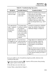
... with the corresponding mark on the card to power on the camera. B-3 Incorrect focus, optional lenses, or 20-mm lens not properly aligned. Visible light and IR images are downloaded to the SmartView software. Adjust the alignment after the images are not properly aligned. Align the... 20-mm lens such that the white alignment marking on the lens lines up storage device (e.g., CD-R disc). If this still does not correct the issue: Contact Fluke...
... with the corresponding mark on the card to power on the camera. B-3 Incorrect focus, optional lenses, or 20-mm lens not properly aligned. Visible light and IR images are downloaded to the SmartView software. Adjust the alignment after the images are not properly aligned. Align the... 20-mm lens such that the white alignment marking on the lens lines up storage device (e.g., CD-R disc). If this still does not correct the issue: Contact Fluke...
