Fluke 726 Process Calibrator Datasheet
Page 1
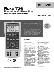
...; Two separate channels; Fluke 726 Precision Multifunction Process Calibrator Technical Data More Calibration Power! Pressure Enabled For more detailed information visit www.fluke.com/726 726 features: • More precise measurement and calibration source performance, accuracies of 0.01%. • Transmitter error% calculation, interpret calibration results without the help of a switch • Custom RTD curves, add calibration constants...
...; Two separate channels; Fluke 726 Precision Multifunction Process Calibrator Technical Data More Calibration Power! Pressure Enabled For more detailed information visit www.fluke.com/726 726 features: • More precise measurement and calibration source performance, accuracies of 0.01%. • Transmitter error% calculation, interpret calibration results without the help of a switch • Custom RTD curves, add calibration constants...
Fluke 726 Process Calibrator Datasheet
Page 2
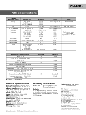
... supply 100.00 mV DC 30.000 V DC measure 20.000 V DC measure, 20.000 VDC Source 5 to 4000 Ohms Thermocouple J, K, T, E, R, S, B, M, L, U, N, C, BP, XK RTD Ni120; Pt100, 200, 500, 1000 (385), Cu 10 Pressure (requires Fluke 700PXX Modules) Frequency; 726 Specifications Function Measure or Source Voltage mA mV (TC terminals) Resistance Frequency Loop Supply Thermocouples Thermocouples...
... supply 100.00 mV DC 30.000 V DC measure 20.000 V DC measure, 20.000 VDC Source 5 to 4000 Ohms Thermocouple J, K, T, E, R, S, B, M, L, U, N, C, BP, XK RTD Ni120; Pt100, 200, 500, 1000 (385), Cu 10 Pressure (requires Fluke 700PXX Modules) Frequency; 726 Specifications Function Measure or Source Voltage mA mV (TC terminals) Resistance Frequency Loop Supply Thermocouples Thermocouples...
FE 726 Users Manual
Page 4
726 Users Manual HART Resistor ON/OFF 16 Getting Started ...16 Voltage to Voltage Test 16 Using Measure Mode ...18 Measuring Electrical Parameters (Upper Display 18 Current Measurement with Loop Power 18 Measuring Electrical Parameters (Lower Display 20 Measuring Temperature 21 Using Thermocouples 21 Using Resistance-Temperature Detectors (RTDs... Zeroing with Absolute Pressure Modules 28 Using Source Mode...30 Sourcing 4 to 20-mA Transmitter 30 Sourcing Other Electrical Parameters 32 Simulating Thermocouples 34 Simulating RTDs ...36 Sourcing Pressure...38 Setting 0 % and 100...
726 Users Manual HART Resistor ON/OFF 16 Getting Started ...16 Voltage to Voltage Test 16 Using Measure Mode ...18 Measuring Electrical Parameters (Upper Display 18 Current Measurement with Loop Power 18 Measuring Electrical Parameters (Lower Display 20 Measuring Temperature 21 Using Thermocouples 21 Using Resistance-Temperature Detectors (RTDs... Zeroing with Absolute Pressure Modules 28 Using Source Mode...30 Sourcing 4 to 20-mA Transmitter 30 Sourcing Other Electrical Parameters 32 Simulating Thermocouples 34 Simulating RTDs ...36 Sourcing Pressure...38 Setting 0 % and 100...
FE 726 Users Manual
Page 5
Contents (continued) Storing and Recalling Data 43 Storing Data...43 Recall Data ...44 Pulse Train Source/Read 44 Calibrating a Transmitter 45 Calibrating a Pressure Transmitter 47 Calibrating an I/P Device 49 Pressure Switch Test...51 Testing ... 54 Replacement Parts 54 Accessories ...56 External Fluke Pressure Module Compatibility 56 Specifications ...59 DC Voltage Measurement and Source 59 DC mA Measurement and Source 59 Ohms Measurement 60 Ohms Source...60 Frequency Measurement 60 Frequency Source ...61 Temperature, Thermocouples 61 RTD Accuracy (Read and Source) (ITS-90 63 iii
Contents (continued) Storing and Recalling Data 43 Storing Data...43 Recall Data ...44 Pulse Train Source/Read 44 Calibrating a Transmitter 45 Calibrating a Pressure Transmitter 47 Calibrating an I/P Device 49 Pressure Switch Test...51 Testing ... 54 Replacement Parts 54 Accessories ...56 External Fluke Pressure Module Compatibility 56 Specifications ...59 DC Voltage Measurement and Source 59 DC mA Measurement and Source 59 Ohms Measurement 60 Ohms Source...60 Frequency Measurement 60 Frequency Source ...61 Temperature, Thermocouples 61 RTD Accuracy (Read and Source) (ITS-90 63 iii
FE 726 Users Manual
Page 7
Pressure Modules...57 v Key Functions...11 5. Thermocouple Types Accepted 22 6. RTD Types Accepted...25 7. Fluke Pressure Module Compatibility 56 10. List of Source and Measure Functions 2 2. Input/Output Terminals and Connectors 9 4. Summary of Tables Table Title Page 1. Replacement Parts ...54 9. mA Step Values ...42 8. International Symbols ...7 3.
Pressure Modules...57 v Key Functions...11 5. Thermocouple Types Accepted 22 6. RTD Types Accepted...25 7. Fluke Pressure Module Compatibility 56 10. List of Source and Measure Functions 2 2. Input/Output Terminals and Connectors 9 4. Summary of Tables Table Title Page 1. Replacement Parts ...54 9. mA Step Values ...42 8. International Symbols ...7 3.
FE 726 Users Manual
Page 9
... ...14 6. Measuring Voltage and Current Output 18 8. Measuring Temperature with an RTD, Measuring 2-, 3-, and 4-Wire Resistance 26 12. Measuring Temperature with a Thermocouple 23 11. Connections for Simulating a Thermocouple 35 17. Connections for Simulating a 4- Connection for Measuring Pressure 29 14. Electrical Sourcing Connections 33 16. Elements of Figures Figure Title Page 1. Measuring Electrical...
... ...14 6. Measuring Voltage and Current Output 18 8. Measuring Temperature with an RTD, Measuring 2-, 3-, and 4-Wire Resistance 26 12. Measuring Temperature with a Thermocouple 23 11. Connections for Simulating a Thermocouple 35 17. Connections for Simulating a 4- Connection for Measuring Pressure 29 14. Electrical Sourcing Connections 33 16. Elements of Figures Figure Title Page 1. Measuring Electrical...
FE 726 Users Manual
Page 12
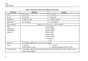
... Measure Functions 0 V to 30 V Measure 0 V to 20 V Source 0 to 24 mA 0 to 24 mA 2 CPM to 15 kHz 0 Ω to 4000 Ω 2 CPM to 15 kHz 5 Ω to 10 kHz Loop supply, HART ... Ω (385) Pt100 Ω (3926) Pt100 Ω (3916) Pt200 Ω (385) Pt500 Ω (385) Pt1000 Ω (385) Ni120 (672) CU10 29 modules ranging from 1.0 in. 726 Users Manual Function dc V dc mA Frequency Resistance Thermocouple RTD (ResistanceTemperature Detector) Pressure Pulse Other functions 2 Table 1.
... Measure Functions 0 V to 30 V Measure 0 V to 20 V Source 0 to 24 mA 0 to 24 mA 2 CPM to 15 kHz 0 Ω to 4000 Ω 2 CPM to 15 kHz 5 Ω to 10 kHz Loop supply, HART ... Ω (385) Pt100 Ω (3926) Pt100 Ω (3916) Pt200 Ω (385) Pt500 Ω (385) Pt1000 Ω (385) Ni120 (672) CU10 29 modules ranging from 1.0 in. 726 Users Manual Function dc V dc mA Frequency Resistance Thermocouple RTD (ResistanceTemperature Detector) Pressure Pulse Other functions 2 Table 1.
FE 726 Users Manual
Page 16
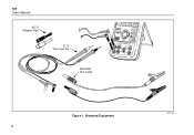
Standard Equipment bec01f.eps 6 RTD LOOP 4W COM COM Figure 1. 726 Users Manual AC72 Alligator Clips TL75 Test Lead Set Stackable Test Leads FREQ TC RTD PULSE CONFIG SELECTION SAVE RECALL ENTER EXIT CONFIG 100% 25% TRIGGER/STOP 25% Return to 0% Recall SOURCE mA+ / 30V MAX MEASURE ALL TERMINALS 3W V Hz MEASURE TC V mA mA-
Standard Equipment bec01f.eps 6 RTD LOOP 4W COM COM Figure 1. 726 Users Manual AC72 Alligator Clips TL75 Test Lead Set Stackable Test Leads FREQ TC RTD PULSE CONFIG SELECTION SAVE RECALL ENTER EXIT CONFIG 100% 25% TRIGGER/STOP 25% Return to 0% Recall SOURCE mA+ / 30V MAX MEASURE ALL TERMINALS 3W V Hz MEASURE TC V mA mA-
FE 726 Users Manual
Page 18
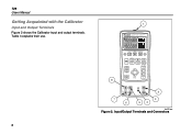
Table 3 explains their use. 8 1 726 PRECISION CALIBRATOR %Error V mA LOOP ZERO 3 Seconds OPEN/CLOSE SWITCH TEST MEAS SOURCE HART V mA TC RTD FREQ PULSE CONFIG SELECTION EXIT CONFIG 100% SAVE RECALL 25% ENTER 25% TRIGGER/STOP RReReRtteueucrcrnanaltlltoo 0% 8 2 7 6 3 54 bec05f.eps Figure 2. Input/Output Terminals and Connectors 726 Users Manual Getting Acquainted with the Calibrator Input and Output Terminals Figure 2 shows the Calibrator input and output terminals.
Table 3 explains their use. 8 1 726 PRECISION CALIBRATOR %Error V mA LOOP ZERO 3 Seconds OPEN/CLOSE SWITCH TEST MEAS SOURCE HART V mA TC RTD FREQ PULSE CONFIG SELECTION EXIT CONFIG 100% SAVE RECALL 25% ENTER 25% TRIGGER/STOP RReReRtteueucrcrnanaltlltoo 0% 8 2 7 6 3 54 bec05f.eps Figure 2. Input/Output Terminals and Connectors 726 Users Manual Getting Acquainted with the Calibrator Input and Output Terminals Figure 2 shows the Calibrator input and output terminals.
FE 726 Users Manual
Page 19
... and Connectors Name Description Pressure module connector/serial connector Connects the Calibrator to a pressure module or to center. Thermocouple (TC) input/output Terminal for sourcing and measuring current and performing 3 W and 4 W RTD measurements. HART resistor option in ) center to a PC for measuring voltage, current, supplying loop power, HART resistance, switch test options...
... and Connectors Name Description Pressure module connector/serial connector Connects the Calibrator to a pressure module or to center. Thermocouple (TC) input/output Terminal for sourcing and measuring current and performing 3 W and 4 W RTD measurements. HART resistor option in ) center to a PC for measuring voltage, current, supplying loop power, HART resistance, switch test options...
FE 726 Users Manual
Page 20
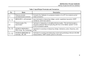
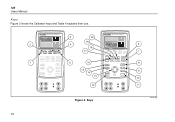
... Manual Keys Figure 3 shows the Calibrator keys and Table 4 explains their use. 2 1 726 PRECISION CALIBRATOR %Error V mA LOOP ZERO 3 Seconds OPEN/CLOSE SWITCH TEST MEAS SOURCE HART V mA TC RTD FREQ PULSE CONFIG SELECTION SAVE RECALL ENTER TRIGGER/STOP Return to Recal EXIT CONFIG 100% 25% 25% 0% 3 4 5 ...20 19 18 17 16 15 14 13 12 726 PRECISION CALIBRATOR %Error V mA LOOP ZERO 3 Seconds OPEN/CLOSE SWITCH TEST MEAS SOURCE HART V mA TC RTD FREQ PULSE CONFIG SELECTION SAVE RECALL ENTER TRIGGER/STOP Return to Recallurn to Recal EXIT CONFIG 100% ...
... Manual Keys Figure 3 shows the Calibrator keys and Table 4 explains their use. 2 1 726 PRECISION CALIBRATOR %Error V mA LOOP ZERO 3 Seconds OPEN/CLOSE SWITCH TEST MEAS SOURCE HART V mA TC RTD FREQ PULSE CONFIG SELECTION SAVE RECALL ENTER TRIGGER/STOP Return to Recal EXIT CONFIG 100% 25% 25% 0% 3 4 5 ...20 19 18 17 16 15 14 13 12 726 PRECISION CALIBRATOR %Error V mA LOOP ZERO 3 Seconds OPEN/CLOSE SWITCH TEST MEAS SOURCE HART V mA TC RTD FREQ PULSE CONFIG SELECTION SAVE RECALL ENTER TRIGGER/STOP Return to Recallurn to Recal EXIT CONFIG 100% ...
FE 726 Users Manual
Page 22
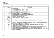
... through the memory locations of Calibrator setups. Q T Selects TC (thermocouple) measurement and sourcing function in the configuration menus. Inserts a 250 Ω resistor when in lower display. Selects resistance mode. T U Selects the pressure ...measurement and sourcing function. 726 Users Manual Table 4. O C Used to Recall Increases or decreases the source level. P M Cycles the Calibrator through the RTD types. S R Selects RTD (resistance temperature detector) measurement and sourcing function in mA. Repeated pushes cycle through MEASURE and SOURCE modes in ...
... through the memory locations of Calibrator setups. Q T Selects TC (thermocouple) measurement and sourcing function in the configuration menus. Inserts a 250 Ω resistor when in lower display. Selects resistance mode. T U Selects the pressure ...measurement and sourcing function. 726 Users Manual Table 4. O C Used to Recall Increases or decreases the source level. P M Cycles the Calibrator through the RTD types. S R Selects RTD (resistance temperature detector) measurement and sourcing function in mA. Repeated pushes cycle through MEASURE and SOURCE modes in ...
FE 726 Users Manual
Page 24
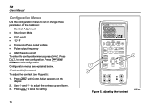
... down. 3. Use X and W to exit configuration. Adjusting the Contrast bec06f.eps 726 Users Manual Configuration Menus Use the configuration menus to save the setting. 14 726 PRECISION CALIBRATOR 1 3 %Error V mA LOOP ZERO 3 Seconds OPEN/CLOSE SWITCH TEST MEAS SOURCE HART V mA TC RTD FREQ PULSE CONFIG SELECTION EXIT CONFIG 2 100% SAVE RECALL ENTER TRIGGER...
... down. 3. Use X and W to exit configuration. Adjusting the Contrast bec06f.eps 726 Users Manual Configuration Menus Use the configuration menus to save the setting. 14 726 PRECISION CALIBRATOR 1 3 %Error V mA LOOP ZERO 3 Seconds OPEN/CLOSE SWITCH TEST MEAS SOURCE HART V mA TC RTD FREQ PULSE CONFIG SELECTION EXIT CONFIG 2 100% SAVE RECALL ENTER TRIGGER...
FE 726 Users Manual
Page 27
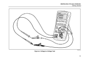
Voltage-to-Voltage Test bec39f.eps 17 Multifunction Process Calibrator Getting Started 726 PRECISION CALIBRATOR %Error V mA LOOP ZERO 3 Seconds OPEN/CLOSE STWEISTTCH MEAS SOURCE CONFIG SELECTION SAVE RECALL ENTER TRIGGER/STOP HART V mA TC RTD FREQ PULSE EXIT CONFIG 100% 25% 25% 0% Figure 6.
Voltage-to-Voltage Test bec39f.eps 17 Multifunction Process Calibrator Getting Started 726 PRECISION CALIBRATOR %Error V mA LOOP ZERO 3 Seconds OPEN/CLOSE STWEISTTCH MEAS SOURCE CONFIG SELECTION SAVE RECALL ENTER TRIGGER/STOP HART V mA TC RTD FREQ PULSE EXIT CONFIG 100% 25% 25% 0% Figure 6.
FE 726 Users Manual
Page 29
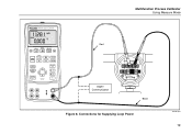
Connections for Supplying Loop Power bec18f.eps 19 Multifunction Process Calibrator Using Measure Mode 726 PRECISION CALIBRATOR %Error V mA LOOP ZERO 3 Seconds OPEN/CLOSE SWITCH TEST MEAS SOURCE HART V mA TC RTD FREQ PULSE CONFIG SELECTION SAVE RECALL ENTER TRIGGER/STOP Return to Recall EXIT CONFIG 100% 25% 25% 0% Red HART Communicator TEST DC PWR - ++ - +- Black Figure 8.
Connections for Supplying Loop Power bec18f.eps 19 Multifunction Process Calibrator Using Measure Mode 726 PRECISION CALIBRATOR %Error V mA LOOP ZERO 3 Seconds OPEN/CLOSE SWITCH TEST MEAS SOURCE HART V mA TC RTD FREQ PULSE CONFIG SELECTION SAVE RECALL ENTER TRIGGER/STOP Return to Recall EXIT CONFIG 100% 25% 25% 0% Red HART Communicator TEST DC PWR - ++ - +- Black Figure 8.
FE 726 Users Manual
Page 30
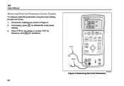
... lower display, proceed as shown in Figure 9. If necessary, press for frequency, and Rfor resistance. 20 726 PRECISION CALIBRATOR Red Black %Error V mA LOOP ZERO 3 Seconds OPEN/CLOSE SWITCH TEST MEAS SOURCE HART V mA TC RTD FREQ PULSE CONFIG SELECTION SAVE RECALL ENTER TRIGGER/STOP Return to Recal EXIT CONFIG 100% 25% 25...
... lower display, proceed as shown in Figure 9. If necessary, press for frequency, and Rfor resistance. 20 726 PRECISION CALIBRATOR Red Black %Error V mA LOOP ZERO 3 Seconds OPEN/CLOSE SWITCH TEST MEAS SOURCE HART V mA TC RTD FREQ PULSE CONFIG SELECTION SAVE RECALL ENTER TRIGGER/STOP Return to Recal EXIT CONFIG 100% 25% 25...
FE 726 Users Manual
Page 33
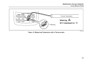
Multifunction Process Calibrator Using Measure Mode 30V MAX ALL TERMINALS SOURCE / MEASURE mA+ 3W V TC Hz RTD MEASURE V mA LOOP mA- TC 4W COM COM TC Miniplug Process Temperature Warning 30 V maximum to Figure 10. Measuring Temperature with a Thermocouple bec12f.eps 23
Multifunction Process Calibrator Using Measure Mode 30V MAX ALL TERMINALS SOURCE / MEASURE mA+ 3W V TC Hz RTD MEASURE V mA LOOP mA- TC 4W COM COM TC Miniplug Process Temperature Warning 30 V maximum to Figure 10. Measuring Temperature with a Thermocouple bec12f.eps 23

FE 726 Users Manual
Page 36
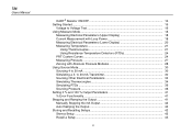
726 Users Manual 2W 30V MAX ALL TERMINALS SOURCE / MEASURE mA+ 3W V TC Hz RTD MEASURE V mA LOOP mA- 4W COM COM 3W 30V MAX ALL TERMINALS SOURCE / MEASURE mA+ 3W V TC Hz RTD MEASURE V mA LOOP mA- 4W COM COM RTD RTD 4W 30V MAX ALL TERMINALS SOURCE / MEASURE mA+ 3W V TC Hz RTD MEASURE V mA LOOP mA- 4W COM COM RTD Figure 11. Measuring Temperature with an RTD, Measuring 2-, 3-, and 4-Wire Resistance bec15f.eps 26
726 Users Manual 2W 30V MAX ALL TERMINALS SOURCE / MEASURE mA+ 3W V TC Hz RTD MEASURE V mA LOOP mA- 4W COM COM 3W 30V MAX ALL TERMINALS SOURCE / MEASURE mA+ 3W V TC Hz RTD MEASURE V mA LOOP mA- 4W COM COM RTD RTD 4W 30V MAX ALL TERMINALS SOURCE / MEASURE mA+ 3W V TC Hz RTD MEASURE V mA LOOP mA- 4W COM COM RTD Figure 11. Measuring Temperature with an RTD, Measuring 2-, 3-, and 4-Wire Resistance bec15f.eps 26
FE 726 Users Manual
Page 39
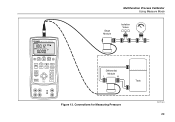
Connections for Measuring Pressure bec37f.eps 29 726 PRECISION CALIBRATOR %Error V mA LOOP ZERO 3 Seconds OPEN/CLOSE SWITCH TEST MEAS SOURCE HART V mA TC RTD FREQ PULSE CONFIG SELECTION SAVE RECALL ENTER TRIGGER/STOP Return to Recall EXIT CONFIG 100% 25% 25% 0% Multifunction Process Calibrator Using Measure Mode Gage Module Isolation Valve Differential Module L H Tank Figure 13.
Connections for Measuring Pressure bec37f.eps 29 726 PRECISION CALIBRATOR %Error V mA LOOP ZERO 3 Seconds OPEN/CLOSE SWITCH TEST MEAS SOURCE HART V mA TC RTD FREQ PULSE CONFIG SELECTION SAVE RECALL ENTER TRIGGER/STOP Return to Recall EXIT CONFIG 100% 25% 25% 0% Multifunction Process Calibrator Using Measure Mode Gage Module Isolation Valve Differential Module L H Tank Figure 13.
FE 726 Users Manual
Page 40
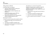
... and Z. 30 Proceed as follows: 1. If necessary, press for SOURCE mode. 3. Press V until both mA and SIM display. 4. M 2. Simulating a 4- 726 Users Manual Using Source Mode In SOURCE mode, the Calibrator: • generates calibrated signals for testing and ...calibrating process instruments • supplies voltages, currents, frequencies, and resistances • simulates the electrical output of operation in which the Calibrator is a special mode of RTD...
... and Z. 30 Proceed as follows: 1. If necessary, press for SOURCE mode. 3. Press V until both mA and SIM display. 4. M 2. Simulating a 4- 726 Users Manual Using Source Mode In SOURCE mode, the Calibrator: • generates calibrated signals for testing and ...calibrating process instruments • supplies voltages, currents, frequencies, and resistances • simulates the electrical output of operation in which the Calibrator is a special mode of RTD...