Fluke 726 Process Calibrator Datasheet
Page 2
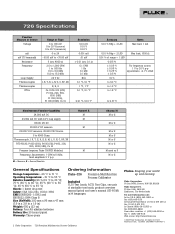
...kHz; Pt100, 200, 500, 1000 (385), Cu 10 Pressure (requires Fluke 700PXX Modules) Frequency; Fluke Corporation PO Box 9090, Everett, WA USA 98206 Fluke Europe B.V. 726 Specifications Function Measure or Source Voltage mA mV (TC terminals) Resistance Frequency ... manual (print) and user's manual (CD-ROM) in14 languages. 2 Fluke Corporation 726 Precision Multifunction Process Calibrator Fluke. Printed in ) Weight: 650 g (23 oz) Battery: Four AA alkaline batteries Battery life: 25 hours typical Warranty: Three-years Ordering Information Fluke-726 Precision Multifunction Process Calibrator...
...kHz; Pt100, 200, 500, 1000 (385), Cu 10 Pressure (requires Fluke 700PXX Modules) Frequency; Fluke Corporation PO Box 9090, Everett, WA USA 98206 Fluke Europe B.V. 726 Specifications Function Measure or Source Voltage mA mV (TC terminals) Resistance Frequency ... manual (print) and user's manual (CD-ROM) in14 languages. 2 Fluke Corporation 726 Precision Multifunction Process Calibrator Fluke. Printed in ) Weight: 650 g (23 oz) Battery: Four AA alkaline batteries Battery life: 25 hours typical Warranty: Three-years Ordering Information Fluke-726 Precision Multifunction Process Calibrator...
FE 726 Users Manual
Page 18
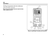
Table 3 explains their use. 8 1 726 PRECISION CALIBRATOR %Error V mA LOOP ZERO 3 Seconds OPEN/CLOSE SWITCH TEST MEAS SOURCE HART V mA TC RTD FREQ PULSE CONFIG SELECTION EXIT CONFIG 100% SAVE RECALL 25% ENTER 25% TRIGGER/STOP RReReRtteueucrcrnanaltlltoo 0% 8 2 7 6 3 54 bec05f.eps Figure 2. Input/Output Terminals and Connectors 726 Users Manual Getting Acquainted with the Calibrator Input and Output Terminals Figure 2 shows the Calibrator input and output terminals.
Table 3 explains their use. 8 1 726 PRECISION CALIBRATOR %Error V mA LOOP ZERO 3 Seconds OPEN/CLOSE SWITCH TEST MEAS SOURCE HART V mA TC RTD FREQ PULSE CONFIG SELECTION EXIT CONFIG 100% SAVE RECALL 25% ENTER 25% TRIGGER/STOP RReReRtteueucrcrnanaltlltoo 0% 8 2 7 6 3 54 bec05f.eps Figure 2. Input/Output Terminals and Connectors 726 Users Manual Getting Acquainted with the Calibrator Input and Output Terminals Figure 2 shows the Calibrator input and output terminals.
FE 726 Users Manual
Page 20
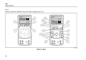
726 Users Manual Keys Figure 3 shows the Calibrator keys and Table 4 explains their use. 2 1 726 PRECISION CALIBRATOR %Error V mA LOOP ZERO 3 Seconds OPEN/CLOSE SWITCH TEST MEAS SOURCE HART V mA TC RTD FREQ PULSE CONFIG SELECTION SAVE RECALL ENTER TRIGGER/STOP Return ...to Recal EXIT CONFIG 100% 25% 25% 0% 3 4 5 20 19 18 17 16 15 14 13 12 726 PRECISION CALIBRATOR %Error V mA LOOP ZERO 3 Seconds OPEN/CLOSE SWITCH TEST MEAS SOURCE HART V mA TC RTD FREQ PULSE CONFIG SELECTION SAVE RECALL ENTER TRIGGER/STOP Return...
726 Users Manual Keys Figure 3 shows the Calibrator keys and Table 4 explains their use. 2 1 726 PRECISION CALIBRATOR %Error V mA LOOP ZERO 3 Seconds OPEN/CLOSE SWITCH TEST MEAS SOURCE HART V mA TC RTD FREQ PULSE CONFIG SELECTION SAVE RECALL ENTER TRIGGER/STOP Return ...to Recal EXIT CONFIG 100% 25% 25% 0% 3 4 5 20 19 18 17 16 15 14 13 12 726 PRECISION CALIBRATOR %Error V mA LOOP ZERO 3 Seconds OPEN/CLOSE SWITCH TEST MEAS SOURCE HART V mA TC RTD FREQ PULSE CONFIG SELECTION SAVE RECALL ENTER TRIGGER/STOP Return...
FE 726 Users Manual
Page 24
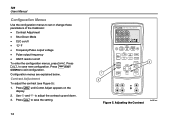
... to adjust the contrast up and down. 3. Configuration menus are explained below. Use X and W to save the setting. 14 726 PRECISION CALIBRATOR 1 3 %Error V mA LOOP ZERO 3 Seconds OPEN/CLOSE SWITCH TEST MEAS SOURCE HART V mA TC RTD FREQ PULSE CONFIG SELECTION...adjust the contrast (see Figure 5): 1. Press S to exit configuration. Adjusting the Contrast bec06f.eps 726 Users Manual Configuration Menus Use the configuration menus to set or change these parameters of the Calibrator: • Contrast Adjustment • Shut Down Mode • CJC on/off To enter the ...
... to adjust the contrast up and down. 3. Configuration menus are explained below. Use X and W to save the setting. 14 726 PRECISION CALIBRATOR 1 3 %Error V mA LOOP ZERO 3 Seconds OPEN/CLOSE SWITCH TEST MEAS SOURCE HART V mA TC RTD FREQ PULSE CONFIG SELECTION...adjust the contrast (see Figure 5): 1. Press S to exit configuration. Adjusting the Contrast bec06f.eps 726 Users Manual Configuration Menus Use the configuration menus to set or change these parameters of the Calibrator: • Contrast Adjustment • Shut Down Mode • CJC on/off To enter the ...
FE 726 Users Manual
Page 30
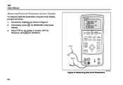
Measuring Electrical Parameters If necessary, press for frequency, and Rfor resistance. 20 726 PRECISION CALIBRATOR Red Black %Error V mA LOOP ZERO 3 Seconds OPEN/CLOSE SWITCH TEST MEAS SOURCE HART V mA TC RTD FREQ PULSE CONFIG...ENTER TRIGGER/STOP Return to Recal EXIT CONFIG 100% 25% 25% 0% bec43f.eps Figure 9. Connect the Calibrator as follows: 1. Press V for dc voltage or current, K for MEASURE mode (lower display). 3. 726 Users Manual Measuring Electrical Parameters (Lower Display) To measure electrical parameters using the lower display, proceed as shown in Figure ...
Measuring Electrical Parameters If necessary, press for frequency, and Rfor resistance. 20 726 PRECISION CALIBRATOR Red Black %Error V mA LOOP ZERO 3 Seconds OPEN/CLOSE SWITCH TEST MEAS SOURCE HART V mA TC RTD FREQ PULSE CONFIG...ENTER TRIGGER/STOP Return to Recal EXIT CONFIG 100% 25% 25% 0% bec43f.eps Figure 9. Connect the Calibrator as follows: 1. Press V for dc voltage or current, K for MEASURE mode (lower display). 3. 726 Users Manual Measuring Electrical Parameters (Lower Display) To measure electrical parameters using the lower display, proceed as shown in Figure ...
FE 726 Users Manual
Page 34
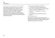
... highest measurement precision, and two-wire provides the lowest measurement precision. Continue pressing this key to input terminals as shown in Figure 11. Attach the RTD to select the desired RTD type. 3. To measure temperature using an RTD input: M 1. The Calibrator accepts RTD measurement... the RTD display. For more information, see the Application Note on the 725/726 CD. 24 Press X or W to six characters. 726 Users Manual Using Resistance-Temperature Detectors (RTDs) The Calibrator accepts RTD types shown in two-, three-, or four-wire connections, with the...
... highest measurement precision, and two-wire provides the lowest measurement precision. Continue pressing this key to input terminals as shown in Figure 11. Attach the RTD to select the desired RTD type. 3. To measure temperature using an RTD input: M 1. The Calibrator accepts RTD measurement... the RTD display. For more information, see the Application Note on the 725/726 CD. 24 Press X or W to six characters. 726 Users Manual Using Resistance-Temperature Detectors (RTDs) The Calibrator accepts RTD types shown in two-, three-, or four-wire connections, with the...
FE 726 Users Manual
Page 50
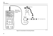
Connections for Sourcing Pressure bec47f.eps 40 726 Users Manual 726 PRECISION CALIBRATOR Measure mA Source Pressure 24 V Loop Power Enabled Hand Pump %Error V mA LOOP ZERO 3 Seconds OPEN/CLOSE SWITCH TEST MEAS SOURCE HART V mA TC RTD FREQ PULSE CONFIG SELECTION SAVE RECALL ENTER TRIGGER/STOP Return to Recall EXIT CONFIG 100% 25% 25% 00%% Pressure Module To Unit Under Test Figure 18.
Connections for Sourcing Pressure bec47f.eps 40 726 Users Manual 726 PRECISION CALIBRATOR Measure mA Source Pressure 24 V Loop Power Enabled Hand Pump %Error V mA LOOP ZERO 3 Seconds OPEN/CLOSE SWITCH TEST MEAS SOURCE HART V mA TC RTD FREQ PULSE CONFIG SELECTION SAVE RECALL ENTER TRIGGER/STOP Return to Recall EXIT CONFIG 100% 25% 25% 00%% Pressure Module To Unit Under Test Figure 18.
FE 726 Users Manual
Page 56
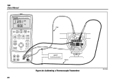
726 Users Manual 726 PRECISION CALIBRATOR %Error V mA LOOP ZERO 3 Seconds OPEN/CLOSE SWITCH TEST MEAS SOURCE HART V mA TC RTD FREQ PULSE CONFIG SELECTION SAVE RECALL ENTER TRIGGER/STOP Return to Recall EXIT CONFIG 100% 25% 25% 0% Red TEST DC PWR - ++ - +- HART Communicator Black Figure 20. Calibrating a Thermocouple Transmitter 46 bec44f.eps
726 Users Manual 726 PRECISION CALIBRATOR %Error V mA LOOP ZERO 3 Seconds OPEN/CLOSE SWITCH TEST MEAS SOURCE HART V mA TC RTD FREQ PULSE CONFIG SELECTION SAVE RECALL ENTER TRIGGER/STOP Return to Recall EXIT CONFIG 100% 25% 25% 0% Red TEST DC PWR - ++ - +- HART Communicator Black Figure 20. Calibrating a Thermocouple Transmitter 46 bec44f.eps
FE 726 Users Manual
Page 58
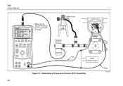
Calibrating a Pressure-to Recall EXIT CONFIG 100% 25% 25% 00%% Pressure Module Red HART Communicator Figure 21. 726 Users Manual 726 PRECISION CALIBRATOR Measure mA Source Pressure 24 V Loop Power Enabled Hand Pump SIGNAL + - TEST %Error V mA LOOP ZERO 3 Seconds OPEN/CLOSE SWITCH TEST MEAS SOURCE HART V mA TC RTD FREQ PULSE CONFIG SELECTION SAVE RECALL ENTER TRIGGER/STOP Return to -Current (P/I) Transmitter 48 Black bec34f.eps
Calibrating a Pressure-to Recall EXIT CONFIG 100% 25% 25% 00%% Pressure Module Red HART Communicator Figure 21. 726 Users Manual 726 PRECISION CALIBRATOR Measure mA Source Pressure 24 V Loop Power Enabled Hand Pump SIGNAL + - TEST %Error V mA LOOP ZERO 3 Seconds OPEN/CLOSE SWITCH TEST MEAS SOURCE HART V mA TC RTD FREQ PULSE CONFIG SELECTION SAVE RECALL ENTER TRIGGER/STOP Return to -Current (P/I) Transmitter 48 Black bec34f.eps
FE 726 Users Manual
Page 60
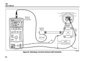
726 Users Manual 726 PRECISION CALIBRATOR Measure Pressure Source mA SIGNAL + - Calibrating a Current-to Recall EXIT CONFIG 100% 25% 25% 00%% Pressure Module Red HART Communicator Figure 22. TEST %Error V mA LOOP ZERO 3 Seconds OPEN/CLOSE SWITCH TEST MEAS SOURCE HART V mA TC RTD FREQ PULSE CONFIG SELECTION SAVE RECALL ENTER TRIGGER/STOP Return to -Pressure (I/P) Transmitter 50 Black bec28f.eps
726 Users Manual 726 PRECISION CALIBRATOR Measure Pressure Source mA SIGNAL + - Calibrating a Current-to Recall EXIT CONFIG 100% 25% 25% 00%% Pressure Module Red HART Communicator Figure 22. TEST %Error V mA LOOP ZERO 3 Seconds OPEN/CLOSE SWITCH TEST MEAS SOURCE HART V mA TC RTD FREQ PULSE CONFIG SELECTION SAVE RECALL ENTER TRIGGER/STOP Return to -Pressure (I/P) Transmitter 50 Black bec28f.eps


