Fluke 726 Process Calibrator Datasheet
Page 2
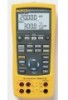
... D-EN-N Rev C Printed in ) Weight: 650 g (23 oz) Battery: Four AA alkaline batteries Battery life: 25 hours typical Warranty: Three-years Ordering Information Fluke-726 Precision Multifunction Process Calibrator Included TL75 Test Leads, AC72 Test Clips, one pair of range + 1 LSD 0.015 % ± 0.05 % ± 0.05 % ± 0.25...% Rdg + 2 LSD Notes Max load, 1 mA 0.01 % Rdg + 2 LSD Max load, 1000 Ω 0.01 % of stackable test leads, product overview manual (print) and user's manual (CD-ROM) in14 languages. 2 Fluke Corporation 726 Precision Multifunction Process Calibrator Fluke.
... D-EN-N Rev C Printed in ) Weight: 650 g (23 oz) Battery: Four AA alkaline batteries Battery life: 25 hours typical Warranty: Three-years Ordering Information Fluke-726 Precision Multifunction Process Calibrator Included TL75 Test Leads, AC72 Test Clips, one pair of range + 1 LSD 0.015 % ± 0.05 % ± 0.05 % ± 0.25...% Rdg + 2 LSD Notes Max load, 1 mA 0.01 % Rdg + 2 LSD Max load, 1000 Ω 0.01 % of stackable test leads, product overview manual (print) and user's manual (CD-ROM) in14 languages. 2 Fluke Corporation 726 Precision Multifunction Process Calibrator Fluke.
FE 726 Users Manual
Page 1
September 2005 © 2005 Fluke Corporation. All rights reserved. All product names are trademarks of their respective companies. ® 726 Multifunction Process Calibrator Users Manual
September 2005 © 2005 Fluke Corporation. All rights reserved. All product names are trademarks of their respective companies. ® 726 Multifunction Process Calibrator Users Manual
FE 726 Users Manual
Page 10
Calibrating a Thermocouple Transmitter 46 21. Calibrating a Pressure-to -Pressure (I ) Transmitter 48 22. SAVE DATA Menu Showing Measurement Memory Location 3, 1 44 20. Calibrating a Current-to -Current (P/I /P) Transmitter 50 23. Replacement Parts...55 viii Replacing the Batteries ...53 25. 726 Users Manual 18. Connections for Sourcing Pressure 40 19. Calibrating a Chart Recorder 52 24.
Calibrating a Thermocouple Transmitter 46 21. Calibrating a Pressure-to -Pressure (I ) Transmitter 48 22. SAVE DATA Menu Showing Measurement Memory Location 3, 1 44 20. Calibrating a Current-to -Current (P/I /P) Transmitter 50 23. Replacement Parts...55 viii Replacing the Batteries ...53 25. 726 Users Manual 18. Connections for Sourcing Pressure 40 19. Calibrating a Chart Recorder 52 24.
FE 726 Users Manual
Page 11
.... • Manual and automatic stepping and ramping. • Stores and recalls calibration screens. • Control the Calibrator remotely from a PC running a terminal emulator program. Contacting Fluke To order accessories, receive operating assistance, or locate the nearest Fluke distributor or Service... To register your product, visit register.fluke.com 1 See Table 1. The lower display allows the user to measure volts, current, and pressure only. Multifunction Process Calibrator Introduction The Fluke 726 Multifunction Process Calibrator (referred to the functions in the ...
.... • Manual and automatic stepping and ramping. • Stores and recalls calibration screens. • Control the Calibrator remotely from a PC running a terminal emulator program. Contacting Fluke To order accessories, receive operating assistance, or locate the nearest Fluke distributor or Service... To register your product, visit register.fluke.com 1 See Table 1. The lower display allows the user to measure volts, current, and pressure only. Multifunction Process Calibrator Introduction The Fluke 726 Multifunction Process Calibrator (referred to the functions in the ...
FE 726 Users Manual
Page 13
... XW Warning To avoid possible electric shock or personal injury, use the Calibrator only as specified in Figure 1) • 725/726 CD-ROM (contains Users Manual; not shown in Figure 1) • 4 AA Batteries (installed) Multifunction Process Calibrator Standard Equipment Safety Information The Calibrator is missing, contact the place of purchase immediately. To order replacement parts...
... XW Warning To avoid possible electric shock or personal injury, use the Calibrator only as specified in Figure 1) • 725/726 CD-ROM (contains Users Manual; not shown in Figure 1) • 4 AA Batteries (installed) Multifunction Process Calibrator Standard Equipment Safety Information The Calibrator is missing, contact the place of purchase immediately. To order replacement parts...
FE 726 Users Manual
Page 14
Protection may be impaired. 726 Users Manual XW Warning To avoid possible electric shock or personal injury: • Use the Calibrator only as described in doubt, have the Calibrator serviced. • Do not operate the Calibrator around explosive gas, vapor, or dust. 4 When disconnecting ...the battery door is damaged. Check test lead continuity. Replace damaged test leads before using the Calibrator. • When using the Calibrator, inspect the case. When in the Users Manual or the protection provided by measuring a known voltage. • Follow all terminals). •...
Protection may be impaired. 726 Users Manual XW Warning To avoid possible electric shock or personal injury: • Use the Calibrator only as described in doubt, have the Calibrator serviced. • Do not operate the Calibrator around explosive gas, vapor, or dust. 4 When disconnecting ...the battery door is damaged. Check test lead continuity. Replace damaged test leads before using the Calibrator. • When using the Calibrator, inspect the case. When in the Users Manual or the protection provided by measuring a known voltage. • Follow all terminals). •...
FE 726 Users Manual
Page 17
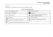
International Symbols AC - Precedes Warning. Multifunction Process Calibrator Safety Information Symbols Symbols used on the Calibrator and in this manual are explained in Table 2. B F J f P ) Table 2. Power ON/OFF Hazardous Voltage. Direct current T M Double insulated Battery Earth ground Pressure Conforms to Canadian Standards Association directives. 7 See Manual. Alternating current DC - Important information. Precedes Warning. Conforms to European Union directives W O X Risk of danger.
International Symbols AC - Precedes Warning. Multifunction Process Calibrator Safety Information Symbols Symbols used on the Calibrator and in this manual are explained in Table 2. B F J f P ) Table 2. Power ON/OFF Hazardous Voltage. Direct current T M Double insulated Battery Earth ground Pressure Conforms to Canadian Standards Association directives. 7 See Manual. Alternating current DC - Important information. Precedes Warning. Conforms to European Union directives W O X Risk of danger.
FE 726 Users Manual
Page 18
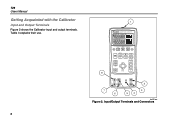
726 Users Manual Getting Acquainted with the Calibrator Input and Output Terminals Figure 2 shows the Calibrator input and output terminals. Table 3 explains their use. 8 1 726 PRECISION CALIBRATOR %Error V mA LOOP ZERO 3 Seconds OPEN/CLOSE SWITCH TEST MEAS SOURCE HART V mA TC RTD FREQ PULSE CONFIG SELECTION EXIT CONFIG 100% SAVE RECALL 25% ENTER 25% TRIGGER/STOP RReReRtteueucrcrnanaltlltoo 0% 8 2 7 6 3 54 bec05f.eps Figure 2. Input/Output Terminals and Connectors
726 Users Manual Getting Acquainted with the Calibrator Input and Output Terminals Figure 2 shows the Calibrator input and output terminals. Table 3 explains their use. 8 1 726 PRECISION CALIBRATOR %Error V mA LOOP ZERO 3 Seconds OPEN/CLOSE SWITCH TEST MEAS SOURCE HART V mA TC RTD FREQ PULSE CONFIG SELECTION EXIT CONFIG 100% SAVE RECALL 25% ENTER 25% TRIGGER/STOP RReReRtteueucrcrnanaltlltoo 0% 8 2 7 6 3 54 bec05f.eps Figure 2. Input/Output Terminals and Connectors
FE 726 Users Manual
Page 20
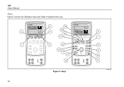
726 Users Manual Keys Figure 3 shows the Calibrator keys and Table 4 explains their use. 2 1 726 PRECISION CALIBRATOR %Error V mA LOOP ZERO 3 Seconds OPEN/CLOSE SWITCH TEST MEAS SOURCE HART V mA TC RTD FREQ PULSE CONFIG SELECTION SAVE RECALL ENTER TRIGGER/STOP Return ...to Recal EXIT CONFIG 100% 25% 25% 0% 3 4 5 20 19 18 17 16 15 14 13 12 726 PRECISION CALIBRATOR %Error V mA LOOP ZERO 3 Seconds OPEN/CLOSE SWITCH TEST MEAS SOURCE HART V mA TC RTD FREQ PULSE CONFIG SELECTION SAVE RECALL ENTER TRIGGER/STOP Return...
726 Users Manual Keys Figure 3 shows the Calibrator keys and Table 4 explains their use. 2 1 726 PRECISION CALIBRATOR %Error V mA LOOP ZERO 3 Seconds OPEN/CLOSE SWITCH TEST MEAS SOURCE HART V mA TC RTD FREQ PULSE CONFIG SELECTION SAVE RECALL ENTER TRIGGER/STOP Return ...to Recal EXIT CONFIG 100% 25% 25% 0% 3 4 5 20 19 18 17 16 15 14 13 12 726 PRECISION CALIBRATOR %Error V mA LOOP ZERO 3 Seconds OPEN/CLOSE SWITCH TEST MEAS SOURCE HART V mA TC RTD FREQ PULSE CONFIG SELECTION SAVE RECALL ENTER TRIGGER/STOP Return...
FE 726 Users Manual
Page 22
... train and totalizer functions. 726 Users Manual Table 4. ENTER is used in the lower display. O C Used to Recall Increases or decreases the source level. Repeated pushes cycle through the memory locations of Calibrator setups. T U Selects the... function. Moves through the RTD types. N S ENTER Saves and recalls setups & data. Repeated pushes cycle through the 2-, 3-, and 4-wire selections. Selects resistance mode. P M Cycles the Calibrator through : E Slow repeating 0 % - 100 % - 0 % ramp L TRIGGER/STOP L P Fast repeating 0 % - 100 % - 0 % ramp N Repeating 0 % - 100 %...
... train and totalizer functions. 726 Users Manual Table 4. ENTER is used in the lower display. O C Used to Recall Increases or decreases the source level. Repeated pushes cycle through the memory locations of Calibrator setups. T U Selects the... function. Moves through the RTD types. N S ENTER Saves and recalls setups & data. Repeated pushes cycle through the 2-, 3-, and 4-wire selections. Selects resistance mode. P M Cycles the Calibrator through : E Slow repeating 0 % - 100 % - 0 % ramp L TRIGGER/STOP L P Fast repeating 0 % - 100 % - 0 % ramp N Repeating 0 % - 100 %...
FE 726 Users Manual
Page 24
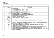
...to save new configuration. Adjusting the Contrast bec06f.eps Use X and W to exit configuration. 726 Users Manual Configuration Menus Use the configuration menus to set or change these parameters of the Calibrator: • Contrast Adjustment • Shut Down Mode • CJC on/off To enter the...; Frequency/Pulse output voltage • Pulse output frequency • HART resistor on the display. 2. Press S, to save the setting. 14 726 PRECISION CALIBRATOR 1 3 %Error V mA LOOP ZERO 3 Seconds OPEN/CLOSE SWITCH TEST MEAS SOURCE HART V mA TC RTD FREQ PULSE CONFIG SELECTION EXIT...
...to save new configuration. Adjusting the Contrast bec06f.eps Use X and W to exit configuration. 726 Users Manual Configuration Menus Use the configuration menus to set or change these parameters of the Calibrator: • Contrast Adjustment • Shut Down Mode • CJC on/off To enter the...; Frequency/Pulse output voltage • Pulse output frequency • HART resistor on the display. 2. Press S, to save the setting. 14 726 PRECISION CALIBRATOR 1 3 %Error V mA LOOP ZERO 3 Seconds OPEN/CLOSE SWITCH TEST MEAS SOURCE HART V mA TC RTD FREQ PULSE CONFIG SELECTION EXIT...
FE 726 Users Manual
Page 26
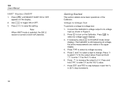
... are visible in the upper display. 4. If necessary, press for the output value. The Calibrator is turned on both mA channels. 16 Getting Started This section details some basic operations of the Calibrator. Press and hold J to select dc voltage (upper display). Use V to -voltage test...toggle ON or OFF. 3. Press Y and Z to select a digit to save the setting. Press S to change. 726 Users Manual HART Resistor ON/OFF 1. Press C until SELECT HART ON or OFF appears on the Calibrator. Press l to enter 1 V as the 100 % value. 7. Press and hold G to 5 V.
... are visible in the upper display. 4. If necessary, press for the output value. The Calibrator is turned on both mA channels. 16 Getting Started This section details some basic operations of the Calibrator. Press and hold J to select dc voltage (upper display). Use V to -voltage test...toggle ON or OFF. 3. Press Y and Z to select a digit to save the setting. Press S to change. 726 Users Manual HART Resistor ON/OFF 1. Press C until SELECT HART ON or OFF appears on the Calibrator. Press l to enter 1 V as the 100 % value. 7. Press and hold G to 5 V.
FE 726 Users Manual
Page 28
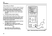
726 Users Manual Using Measure Mode Measuring Electrical Parameters (Upper Display) To measure the current or voltage output of a ... internal 24 V loop supply turns on . 2. Press l to test a transmitter when it is disconnected from plant wiring. Connect the Calibrator to the transmitter current loop terminals as follows: 1. Connect the leads as shown in current measurement mode. LOOP should not be on ....circuit, allowing you to select volts or current. Measuring Voltage and Current Output Press l while the Calibrator is turned on both mA channels. 18 bec42f.eps Figure 7.
726 Users Manual Using Measure Mode Measuring Electrical Parameters (Upper Display) To measure the current or voltage output of a ... internal 24 V loop supply turns on . 2. Press l to test a transmitter when it is disconnected from plant wiring. Connect the Calibrator to the transmitter current loop terminals as follows: 1. Connect the leads as shown in current measurement mode. LOOP should not be on ....circuit, allowing you to select volts or current. Measuring Voltage and Current Output Press l while the Calibrator is turned on both mA channels. 18 bec42f.eps Figure 7.
FE 726 Users Manual
Page 30
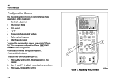
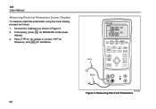
... for dc voltage or current, K for MEASURE mode (lower display). 3. Connect the Calibrator as follows: 1. Measuring Electrical Parameters If necessary, press for frequency, and Rfor resistance. 20 726 PRECISION CALIBRATOR Red Black %Error V mA LOOP ZERO 3 Seconds OPEN/CLOSE SWITCH TEST MEAS SOURCE ...HART V mA TC RTD FREQ PULSE CONFIG SELECTION SAVE RECALL ENTER TRIGGER/STOP Return to Recal EXIT CONFIG 100% 25% 25% 0% bec43f.eps Figure 9. M 2. 726 Users Manual ...
... for dc voltage or current, K for MEASURE mode (lower display). 3. Connect the Calibrator as follows: 1. Measuring Electrical Parameters If necessary, press for frequency, and Rfor resistance. 20 726 PRECISION CALIBRATOR Red Black %Error V mA LOOP ZERO 3 Seconds OPEN/CLOSE SWITCH TEST MEAS SOURCE ...HART V mA TC RTD FREQ PULSE CONFIG SELECTION SAVE RECALL ENTER TRIGGER/STOP Return to Recal EXIT CONFIG 100% 25% 25% 0% bec43f.eps Figure 9. M 2. 726 Users Manual ...
FE 726 Users Manual
Page 34
...mode. 2. Press X or W to input terminals as shown in Figure 11. Names can be up to select the desired RTD type. 3. The Calibrator accepts RTD measurement inputs in Table 6. If necessary, press for the RTD display. To measure temperature using an RTD input: M 1. PRT Custom ... coefficients can be entered through the serial port. Continue pressing this key to six characters. The most common. 726 Users Manual Using Resistance-Temperature Detectors (RTDs) The Calibrator accepts RTD types shown in two-, three-, or four-wire connections, with the three-wire connection the most ...
...mode. 2. Press X or W to input terminals as shown in Figure 11. Names can be up to select the desired RTD type. 3. The Calibrator accepts RTD measurement inputs in Table 6. If necessary, press for the RTD display. To measure temperature using an RTD input: M 1. PRT Custom ... coefficients can be entered through the serial port. Continue pressing this key to six characters. The most common. 726 Users Manual Using Resistance-Temperature Detectors (RTDs) The Calibrator accepts RTD types shown in two-, three-, or four-wire connections, with the three-wire connection the most ...
FE 726 Users Manual
Page 38
...to ¼ ISO adapter if necessary. 2. Use the supplied ¼ NPT to exit the zeroing procedure. Zeroing with Absolute Pressure Modules To zero, adjust the Calibrator to psi, mmHg, inHg, cmH2O@4 °C, cmH2O@20 °C, inH2O@4 °C, inH O@20 2 °C, inH O@60 2 °F, mbar, ...A to change pressure display units to read a known pressure. This can also apply a pressure within range for any absolute pressure module. 726 Users Manual • Never apply pressure above the rated maximum printed on the pressure module. • Only use it is accurately known, for all...
...to ¼ ISO adapter if necessary. 2. Use the supplied ¼ NPT to exit the zeroing procedure. Zeroing with Absolute Pressure Modules To zero, adjust the Calibrator to psi, mmHg, inHg, cmH2O@4 °C, cmH2O@20 °C, inH2O@4 °C, inH O@20 2 °C, inH O@60 2 °F, mbar, ...A to change pressure display units to read a known pressure. This can also apply a pressure within range for any absolute pressure module. 726 Users Manual • Never apply pressure above the rated maximum printed on the pressure module. • Only use it is accurately known, for all...
FE 726 Users Manual
Page 40
... 1. Sourcing 4 to 20-mA Transmitter Simulate is a special mode of operation in which the Calibrator is connected into a loop in place of RTD and thermocouple temperature sensors • measures gas pressure from an external source, creating... both mA and SIM display. 4. If necessary, press for SOURCE mode. 3. M 2. M 2. 726 Users Manual Using Source Mode In SOURCE mode, the Calibrator: • generates calibrated signals for testing and calibrating process instruments • supplies voltages, currents, frequencies, and resistances • simulates the electrical output of ...
... 1. Sourcing 4 to 20-mA Transmitter Simulate is a special mode of operation in which the Calibrator is connected into a loop in place of RTD and thermocouple temperature sensors • measures gas pressure from an external source, creating... both mA and SIM display. 4. If necessary, press for SOURCE mode. 3. M 2. M 2. 726 Users Manual Using Source Mode In SOURCE mode, the Calibrator: • generates calibrated signals for testing and calibrating process instruments • supplies voltages, currents, frequencies, and resistances • simulates the electrical output of ...
FE 726 Users Manual
Page 44
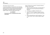
.... One pin is wider than the other. If desired, continue pressing this connection. Enter the temperature you want by pressing X and W keys. 726 Users Manual Simulating Thermocouples Connect the Calibrator TC input/output to the instrument under test with the thermocouple wire and the appropriate thermocouple mini-connector (polarized thermocouple plug with flat...
.... One pin is wider than the other. If desired, continue pressing this connection. Enter the temperature you want by pressing X and W keys. 726 Users Manual Simulating Thermocouples Connect the Calibrator TC input/output to the instrument under test with the thermocouple wire and the appropriate thermocouple mini-connector (polarized thermocouple plug with flat...

FE 726 Users Manual
Page 46
Press R for simulation. 726 Users Manual Simulating RTDs Connect the Calibrator to edit. 4. See Figure 17. 3. Press Y and Z to select a different digit to the instrument under test exceeds the limits of the 726. 36 If the 726 display indicates ExI HI, the excitation current from your device under test as follows to provide the extra wires... in Figure 17. If necessary, press for SOURCE mode. 2. To connect to a 3-wire or 4-wire transmitter, use the stacking cables to simulate an RTD: M 1. The Calibrator simulates a 2-wire RTD at its front panel.
Press R for simulation. 726 Users Manual Simulating RTDs Connect the Calibrator to edit. 4. See Figure 17. 3. Press Y and Z to select a different digit to the instrument under test exceeds the limits of the 726. 36 If the 726 display indicates ExI HI, the excitation current from your device under test as follows to provide the extra wires... in Figure 17. If necessary, press for SOURCE mode. 2. To connect to a 3-wire or 4-wire transmitter, use the stacking cables to simulate an RTD: M 1. The Calibrator simulates a 2-wire RTD at its front panel.
FE 726 Users Manual
Page 48
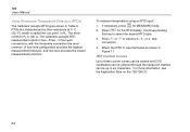
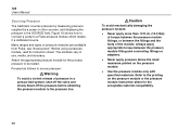
726 Users Manual Sourcing Pressure The Calibrator sources pressure by measuring pressure supplied by a pump or other sources, and displaying the pressure in use, media, and accuracy. WCaution To avoid mechanically damaging ... instruction sheet. The modules vary in the SOURCE field. Always apply appropriate torque between the fittings and the body of pressure modules are available from Fluke, see "Accessories". Many ranges and types of the module. Figure 18 shows how to connect a pump to the printing on the pressure module. • Use...
726 Users Manual Sourcing Pressure The Calibrator sources pressure by measuring pressure supplied by a pump or other sources, and displaying the pressure in use, media, and accuracy. WCaution To avoid mechanically damaging ... instruction sheet. The modules vary in the SOURCE field. Always apply appropriate torque between the fittings and the body of pressure modules are available from Fluke, see "Accessories". Many ranges and types of the module. Figure 18 shows how to connect a pump to the printing on the pressure module. • Use...


