Fluke 726 Process Calibrator Datasheet
Page 1
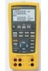
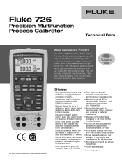
... without a calculator • Memory storage for up to 8 calibration results, return stored calibration data from the field for later analysis • Frequency totalizer and frequency pulse train source mode for improved reliability • Two separate channels; Fluke 726 Precision Multifunction Process Calibrator Technical Data More Calibration Power! The 726 measures and sources almost all process parameters and...
... without a calculator • Memory storage for up to 8 calibration results, return stored calibration data from the field for later analysis • Frequency totalizer and frequency pulse train source mode for improved reliability • Two separate channels; Fluke 726 Precision Multifunction Process Calibrator Technical Data More Calibration Power! The 726 measures and sources almost all process parameters and...
Fluke 726 Process Calibrator Datasheet
Page 2
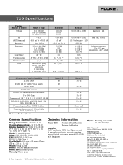
... of stackable test leads, product overview manual (print) and user's manual (CD-ROM) in14 languages. 2 Fluke Corporation 726 Precision Multifunction Process Calibrator Fluke. Pt100, 200, 500, 1000 (385), Cu 10 Pressure (requires Fluke 700PXX Modules) Frequency; fixed amplitude 5 V p-p M = Measure, S = Source/Simulate Channel A M... (23 oz) Battery: Four AA alkaline batteries Battery life: 25 hours typical Warranty: Three-years Ordering Information Fluke-726 Precision Multifunction Process Calibrator Included TL75 Test Leads, AC72 Test Clips, one pair of range + 1 LSD 0.015 % ±...
... of stackable test leads, product overview manual (print) and user's manual (CD-ROM) in14 languages. 2 Fluke Corporation 726 Precision Multifunction Process Calibrator Fluke. Pt100, 200, 500, 1000 (385), Cu 10 Pressure (requires Fluke 700PXX Modules) Frequency; fixed amplitude 5 V p-p M = Measure, S = Source/Simulate Channel A M... (23 oz) Battery: Four AA alkaline batteries Battery life: 25 hours typical Warranty: Three-years Ordering Information Fluke-726 Precision Multifunction Process Calibrator Included TL75 Test Leads, AC72 Test Clips, one pair of range + 1 LSD 0.015 % ±...
FE 726 Users Manual
Page 1
September 2005 © 2005 Fluke Corporation. All rights reserved. All product names are trademarks of their respective companies. ® 726 Multifunction Process Calibrator Users Manual
September 2005 © 2005 Fluke Corporation. All rights reserved. All product names are trademarks of their respective companies. ® 726 Multifunction Process Calibrator Users Manual
FE 726 Users Manual
Page 3
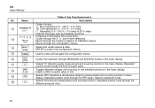
Table of Contents Title Page Introduction...1 Contacting Fluke...1 Standard Equipment...3 Safety Information ...3 Symbols ...7 Getting Acquainted with the Calibrator 8 Input and Output Terminals 8 Keys...10 Display ...13 Configuration Menus ...14 Contrast Adjustment 14 Shut Down Mode ...15 CJC...15 Celcius and Fahrenheit (°C and °F 15 Frequency Pulse Output Voltage 15 Pulse Output Frequency 15 i
Table of Contents Title Page Introduction...1 Contacting Fluke...1 Standard Equipment...3 Safety Information ...3 Symbols ...7 Getting Acquainted with the Calibrator 8 Input and Output Terminals 8 Keys...10 Display ...13 Configuration Menus ...14 Contrast Adjustment 14 Shut Down Mode ...15 CJC...15 Celcius and Fahrenheit (°C and °F 15 Frequency Pulse Output Voltage 15 Pulse Output Frequency 15 i
FE 726 Users Manual
Page 5
...continued) Storing and Recalling Data 43 Storing Data...43 Recall Data ...44 Pulse Train Source/Read 44 Calibrating a Transmitter 45 Calibrating a Pressure Transmitter 47 Calibrating an I/P Device 49 Pressure Switch Test...51 Testing an Output Device 51 Remote Control Commands 52 HART... Functionality...52 Maintenance ...53 Replacing the Batteries 53 Cleaning the Calibrator 54 Service Center Calibration or Repair 54 Replacement Parts 54 Accessories ...56 External Fluke Pressure Module Compatibility 56 Specifications ...59 DC Voltage Measurement and Source 59 DC mA...
...continued) Storing and Recalling Data 43 Storing Data...43 Recall Data ...44 Pulse Train Source/Read 44 Calibrating a Transmitter 45 Calibrating a Pressure Transmitter 47 Calibrating an I/P Device 49 Pressure Switch Test...51 Testing an Output Device 51 Remote Control Commands 52 HART... Functionality...52 Maintenance ...53 Replacing the Batteries 53 Cleaning the Calibrator 54 Service Center Calibration or Repair 54 Replacement Parts 54 Accessories ...56 External Fluke Pressure Module Compatibility 56 Specifications ...59 DC Voltage Measurement and Source 59 DC mA...
FE 726 Users Manual
Page 10
Replacement Parts...55 viii SAVE DATA Menu Showing Measurement Memory Location 3, 1 44 20. Calibrating a Chart Recorder 52 24. 726 Users Manual 18. Connections for Sourcing Pressure 40 19. Calibrating a Thermocouple Transmitter 46 21. Calibrating a Current-to -Current (P/I /P) Transmitter 50 23. Replacing the Batteries ...53 25. Calibrating a Pressure-to -Pressure (I ) Transmitter 48 22.
Replacement Parts...55 viii SAVE DATA Menu Showing Measurement Memory Location 3, 1 44 20. Calibrating a Chart Recorder 52 24. 726 Users Manual 18. Connections for Sourcing Pressure 40 19. Calibrating a Thermocouple Transmitter 46 21. Calibrating a Current-to -Current (P/I /P) Transmitter 50 23. Replacing the Batteries ...53 25. Calibrating a Pressure-to -Pressure (I ) Transmitter 48 22.
FE 726 Users Manual
Page 11
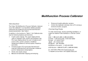
... and functions: • A split-screen display. The lower display allows the user to as "the Calibrator") is a handheld, battery-operated instrument that measures and sources electrical and physical parameters. See Table 1. Multifunction Process Calibrator Introduction The Fluke 726 Multifunction Process Calibrator (referred to measure and source volts, current, pressure, resistance temperature detectors, thermocouples, frequency, and...
... and functions: • A split-screen display. The lower display allows the user to as "the Calibrator") is a handheld, battery-operated instrument that measures and sources electrical and physical parameters. See Table 1. Multifunction Process Calibrator Introduction The Fluke 726 Multifunction Process Calibrator (referred to measure and source volts, current, pressure, resistance temperature detectors, thermocouples, frequency, and...
FE 726 Users Manual
Page 13
...and actions that may be impaired. Standard Equipment If the Calibrator is damaged or something is designed in accordance with the Calibrator. • TL75 test leads • AC72 alligator clips • Stackable alligator clip test leads • 726 Product Overview (not shown in this manual, otherwise the ..., UL 61010-1, and ISA 82.02.01 XW Warning To avoid possible electric shock or personal injury, use the Calibrator only as specified in Figure 1) • 725/726 CD-ROM (contains Users Manual; A Caution identifies conditions and actions that pose hazard(s) to the user. To order...
...and actions that may be impaired. Standard Equipment If the Calibrator is damaged or something is designed in accordance with the Calibrator. • TL75 test leads • AC72 alligator clips • Stackable alligator clip test leads • 726 Product Overview (not shown in this manual, otherwise the ..., UL 61010-1, and ISA 82.02.01 XW Warning To avoid possible electric shock or personal injury, use the Calibrator only as specified in Figure 1) • 725/726 CD-ROM (contains Users Manual; A Caution identifies conditions and actions that pose hazard(s) to the user. To order...
FE 726 Users Manual
Page 14
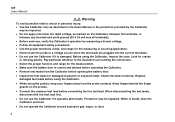
.... Protection may be impaired. • Do not apply more than the rated voltage, as described in doubt, have the Calibrator serviced. • Do not operate the Calibrator around explosive gas, vapor, or dust. 4 Look for damaged insulation or exposed metal. Keep fingers behind the finger guards on... the proper function and range for the measurement. • Make sure the battery door is damaged. 726 Users Manual XW Warning To avoid possible electric shock or personal injury: • Use the Calibrator only as marked on the probes. • Connect the common test lead before using the...
.... Protection may be impaired. • Do not apply more than the rated voltage, as described in doubt, have the Calibrator serviced. • Do not operate the Calibrator around explosive gas, vapor, or dust. 4 Look for damaged insulation or exposed metal. Keep fingers behind the finger guards on... the proper function and range for the measurement. • Make sure the battery door is damaged. 726 Users Manual XW Warning To avoid possible electric shock or personal injury: • Use the Calibrator only as marked on the probes. • Connect the common test lead before using the...
FE 726 Users Manual
Page 15
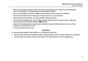
...; Use the proper input jacks, function, and range for the measurement or sourcing application. 5 WCaution To avoid possible damage to the Calibrator or to possible electric shock or personal injury, replace the battery as soon as the battery indicator (M) appears. • Turn off ... module. • Use only 4 AA batteries, properly installed in the Calibrator case, to power the Calibrator. • Disconnect test leads before changing to another measure or source function. • When servicing the Calibrator, use only specified replacement parts. • To avoid false readings, which...
...; Use the proper input jacks, function, and range for the measurement or sourcing application. 5 WCaution To avoid possible damage to the Calibrator or to possible electric shock or personal injury, replace the battery as soon as the battery indicator (M) appears. • Turn off ... module. • Use only 4 AA batteries, properly installed in the Calibrator case, to power the Calibrator. • Disconnect test leads before changing to another measure or source function. • When servicing the Calibrator, use only specified replacement parts. • To avoid false readings, which...
FE 726 Users Manual
Page 17
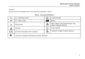
International Symbols AC - Power ON/OFF Hazardous Voltage. Multifunction Process Calibrator Safety Information Symbols Symbols used on the Calibrator and in this manual are explained in Table 2. Alternating current DC - Precedes Warning. See Manual. Precedes Warning. Conforms to European Union directives W O X Risk of danger. Important information. Direct current T M Double insulated Battery Earth ground Pressure Conforms to Canadian Standards Association directives. 7 B F J f P ) Table 2.
International Symbols AC - Power ON/OFF Hazardous Voltage. Multifunction Process Calibrator Safety Information Symbols Symbols used on the Calibrator and in this manual are explained in Table 2. Alternating current DC - Precedes Warning. See Manual. Precedes Warning. Conforms to European Union directives W O X Risk of danger. Important information. Direct current T M Double insulated Battery Earth ground Pressure Conforms to Canadian Standards Association directives. 7 B F J f P ) Table 2.
FE 726 Users Manual
Page 18
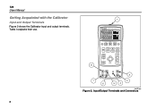
Table 3 explains their use. 8 1 726 PRECISION CALIBRATOR %Error V mA LOOP ZERO 3 Seconds OPEN/CLOSE SWITCH TEST MEAS SOURCE HART V mA TC RTD FREQ PULSE CONFIG SELECTION EXIT CONFIG 100% SAVE RECALL 25% ENTER 25% TRIGGER/STOP RReReRtteueucrcrnanaltlltoo 0% 8 2 7 6 3 54 bec05f.eps Figure 2. Input/Output Terminals and Connectors 726 Users Manual Getting Acquainted with the Calibrator Input and Output Terminals Figure 2 shows the Calibrator input and output terminals.
Table 3 explains their use. 8 1 726 PRECISION CALIBRATOR %Error V mA LOOP ZERO 3 Seconds OPEN/CLOSE SWITCH TEST MEAS SOURCE HART V mA TC RTD FREQ PULSE CONFIG SELECTION EXIT CONFIG 100% SAVE RECALL 25% ENTER 25% TRIGGER/STOP RReReRtteueucrcrnanaltlltoo 0% 8 2 7 6 3 54 bec05f.eps Figure 2. Input/Output Terminals and Connectors 726 Users Manual Getting Acquainted with the Calibrator Input and Output Terminals Figure 2 shows the Calibrator input and output terminals.
FE 726 Users Manual
Page 19
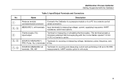
... options. Thermocouple (TC) input/output Terminal for a remote control serial connection. Input/Output Terminals and Connectors Name Description Pressure module connector/serial connector Connects the Calibrator to a pressure module or to center. SOURCE/ MEASURE V, Terminals for sourcing or measuring voltage, resistance, pulse, frequency, and RTD, Pulse, Hz, Ω terminals RTDs. Multifunction...
... options. Thermocouple (TC) input/output Terminal for a remote control serial connection. Input/Output Terminals and Connectors Name Description Pressure module connector/serial connector Connects the Calibrator to a pressure module or to center. SOURCE/ MEASURE V, Terminals for sourcing or measuring voltage, resistance, pulse, frequency, and RTD, Pulse, Hz, Ω terminals RTDs. Multifunction...
FE 726 Users Manual
Page 20
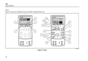
Keys 6 7 8 9 10 11 bec41f.eps 10 726 Users Manual Keys Figure 3 shows the Calibrator keys and Table 4 explains their use. 2 1 726 PRECISION CALIBRATOR %Error V mA LOOP ZERO 3 Seconds OPEN/CLOSE SWITCH TEST MEAS SOURCE HART V mA TC RTD FREQ PULSE CONFIG SELECTION SAVE RECALL ENTER TRIGGER.../STOP Return to Recal EXIT CONFIG 100% 25% 25% 0% 3 4 5 20 19 18 17 16 15 14 13 12 726 PRECISION CALIBRATOR %Error V mA LOOP ZERO 3 Seconds OPEN/CLOSE SWITCH TEST MEAS SOURCE HART V mA TC RTD FREQ PULSE CONFIG SELECTION SAVE RECALL ENTER TRIGGER/STOP ...
Keys 6 7 8 9 10 11 bec41f.eps 10 726 Users Manual Keys Figure 3 shows the Calibrator keys and Table 4 explains their use. 2 1 726 PRECISION CALIBRATOR %Error V mA LOOP ZERO 3 Seconds OPEN/CLOSE SWITCH TEST MEAS SOURCE HART V mA TC RTD FREQ PULSE CONFIG SELECTION SAVE RECALL ENTER TRIGGER.../STOP Return to Recal EXIT CONFIG 100% 25% 25% 0% 3 4 5 20 19 18 17 16 15 14 13 12 726 PRECISION CALIBRATOR %Error V mA LOOP ZERO 3 Seconds OPEN/CLOSE SWITCH TEST MEAS SOURCE HART V mA TC RTD FREQ PULSE CONFIG SELECTION SAVE RECALL ENTER TRIGGER/STOP ...
FE 726 Users Manual
Page 21
... value corresponding to 0 % of span and sets it as the source value. The firmware version is shown in the upper display. Multifunction Process Calibrator Getting Acquainted with the Calibrator Table 4. B %Error l Toggles voltage, mA, or Loop Power and % Error measurement functions in the upper display for 3 seconds. Zeros pressure when held for...
... value corresponding to 0 % of span and sets it as the source value. The firmware version is shown in the upper display. Multifunction Process Calibrator Getting Acquainted with the Calibrator Table 4. B %Error l Toggles voltage, mA, or Loop Power and % Error measurement functions in the upper display for 3 seconds. Zeros pressure when held for...
FE 726 Users Manual
Page 22
..., mA sourcing, or mA simulate functions in the lower display. Repeated pushes cycle through the memory locations of Calibrator setups. Moves through the RTD types. ENTER is used in mA. Inserts a 250 Ω resistor when ...2-, 3-, and 4-wire selections. Q T Selects TC (thermocouple) measurement and sourcing function in lower display. Key Functions (cont.) No Name Description Cycles through the configuration menus. 726 Users Manual Table 4. M XW Y Z Return to enter and navigate the configuration menus. Moves through : E Slow repeating 0 % - 100 % - 0 % ramp L...
..., mA sourcing, or mA simulate functions in the lower display. Repeated pushes cycle through the memory locations of Calibrator setups. Moves through the RTD types. ENTER is used in mA. Inserts a 250 Ω resistor when ...2-, 3-, and 4-wire selections. Q T Selects TC (thermocouple) measurement and sourcing function in lower display. Key Functions (cont.) No Name Description Cycles through the configuration menus. 726 Users Manual Table 4. M XW Y Z Return to enter and navigate the configuration menus. Moves through : E Slow repeating 0 % - 100 % - 0 % ramp L...
FE 726 Users Manual
Page 23
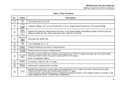
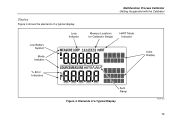
Display Figure 4 shows the elements of a Typical Display bec07f.eps 13 Low Battery Symbol Mode Indicator Loop Indicator Multifunction Process Calibrator Getting Acquainted with the Calibrator Memory Locations for Calibrator Setups HART Mode Indicator Units Display % Error Indicators Auto Ramp Figure 4. Elements of a typical display.
Display Figure 4 shows the elements of a Typical Display bec07f.eps 13 Low Battery Symbol Mode Indicator Loop Indicator Multifunction Process Calibrator Getting Acquainted with the Calibrator Memory Locations for Calibrator Setups HART Mode Indicator Units Display % Error Indicators Auto Ramp Figure 4. Elements of a typical display.
FE 726 Users Manual
Page 24
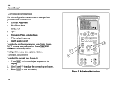
726 Users Manual Configuration Menus Use the configuration menus to set or change these parameters of the Calibrator: • Contrast Adjustment • Shut Down Mode • CJC on/off To enter the configuration menus, press C. Press G/EXIT CONFIG...Figure 5): 1. Press S, to save new configuration. Configuration menus are explained below. Use X and W to exit configuration. Press S to save the setting. 14 726 PRECISION CALIBRATOR 1 3 %Error V mA LOOP ZERO 3 Seconds OPEN/CLOSE SWITCH TEST MEAS SOURCE HART V mA TC RTD FREQ PULSE CONFIG SELECTION EXIT CONFIG 2 100% SAVE...
726 Users Manual Configuration Menus Use the configuration menus to set or change these parameters of the Calibrator: • Contrast Adjustment • Shut Down Mode • CJC on/off To enter the configuration menus, press C. Press G/EXIT CONFIG...Figure 5): 1. Press S, to save new configuration. Configuration menus are explained below. Use X and W to exit configuration. Press S to save the setting. 14 726 PRECISION CALIBRATOR 1 3 %Error V mA LOOP ZERO 3 Seconds OPEN/CLOSE SWITCH TEST MEAS SOURCE HART V mA TC RTD FREQ PULSE CONFIG SELECTION EXIT CONFIG 2 100% SAVE...
FE 726 Users Manual
Page 25
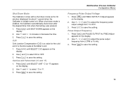
.... 2. Press S to save the setting. 15 Press S to save the setting. Press C until SELECT CJC appears on ). Shut Down Mode The Calibrator comes with a shut down mode set for 30 minutes (displayed for the cold end of a thermocouple at the Meter's end. 1. Press S to save... the setting. Use X and W to save the setting. CJC Cold Junction Compensation (CJC) is a value for about 1 second when the Calibrator is enabled, the Calibrator automatically shuts down after the elapsed time from when the last key was pressed. 1. Press S to save the setting. Multifunction Process...
.... 2. Press S to save the setting. 15 Press S to save the setting. Press C until SELECT CJC appears on ). Shut Down Mode The Calibrator comes with a shut down mode set for 30 minutes (displayed for the cold end of a thermocouple at the Meter's end. 1. Press S to save... the setting. Use X and W to save the setting. CJC Cold Junction Compensation (CJC) is a value for about 1 second when the Calibrator is enabled, the Calibrator automatically shuts down after the elapsed time from when the last key was pressed. 1. Press S to save the setting. Multifunction Process...
FE 726 Users Manual
Page 26
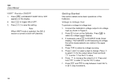
... toggle ON or OFF. 3. Press l to -voltage test: 1. Press C until SELECT HART ON or OFF appears on the Calibrator. Voltage to Voltage Test To perform a voltage-to select dc voltage (upper display). 726 Users Manual HART Resistor ON/OFF 1. Press X to its voltage input as the 100 % value. 7. Note When HART...
... toggle ON or OFF. 3. Press l to -voltage test: 1. Press C until SELECT HART ON or OFF appears on the Calibrator. Voltage to Voltage Test To perform a voltage-to select dc voltage (upper display). 726 Users Manual HART Resistor ON/OFF 1. Press X to its voltage input as the 100 % value. 7. Note When HART...

