Fluke 725 Process Calibrator Datasheet
Page 1
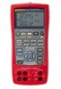
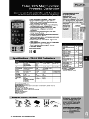
...; Three-year warranty 1 Requires accessory hand pump Understanding specifications for process calibrators. Fluke 725 Multifunction Process Calibrator Easy-to-use field calibrator with functions to test and calibrate almost anything. • Small, streamlined shape makes it easy to carry...manual (CD-ROM) in ) Weight: 650 g (23 oz) Battery: Four AA alkaline batteries Battery life: 25 hours typical Warranty: Three-years Recommended accessories - 725 Calibrator TL75 See page 39 TL220 See page 39 C125 See page 44 ToolPak See page 37 80PK-27 See page 42 For more information, go to www.fluke...
...; Three-year warranty 1 Requires accessory hand pump Understanding specifications for process calibrators. Fluke 725 Multifunction Process Calibrator Easy-to-use field calibrator with functions to test and calibrate almost anything. • Small, streamlined shape makes it easy to carry...manual (CD-ROM) in ) Weight: 650 g (23 oz) Battery: Four AA alkaline batteries Battery life: 25 hours typical Warranty: Three-years Recommended accessories - 725 Calibrator TL75 See page 39 TL220 See page 39 C125 See page 44 ToolPak See page 37 80PK-27 See page 42 For more information, go to www.fluke...

FE 725ex Users Manual
Page 1
Printed in USA All product names are trademarks of their respective companies. ® 725Ex Multifunction Process Calibrator Users Manual January 2005 Rev.1, 8/05 © 2005 Fluke Corporation, All rights reserved.
Printed in USA All product names are trademarks of their respective companies. ® 725Ex Multifunction Process Calibrator Users Manual January 2005 Rev.1, 8/05 © 2005 Fluke Corporation, All rights reserved.
FE 725ex Users Manual
Page 4
725Ex Users Manual Current Measurement with Loop Power 19 Measuring Electrical Parameters (Lower Display 21 Measuring Temperature 22 Using Thermocouples 22 Using Resistance-Temperature Detectors (RTDs 25 Measuring ... Pressure Mode 37 Setting 0 % and 100 % Output Parameters 39 Stepping and Ramping the Output 39 Manually Stepping the mA Output 39 Auto Ramping the Output 40 Storing and Recalling Setups 40 Calibrating a Transmitter 41 Calibrating a Pressure Transmitter 43 Calibrating an I/P Device 45 Switch Test ...47 Testing an Output Device 48 Replacing the Batteries 49...
725Ex Users Manual Current Measurement with Loop Power 19 Measuring Electrical Parameters (Lower Display 21 Measuring Temperature 22 Using Thermocouples 22 Using Resistance-Temperature Detectors (RTDs 25 Measuring ... Pressure Mode 37 Setting 0 % and 100 % Output Parameters 39 Stepping and Ramping the Output 39 Manually Stepping the mA Output 39 Auto Ramping the Output 40 Storing and Recalling Setups 40 Calibrating a Transmitter 41 Calibrating a Pressure Transmitter 43 Calibrating an I/P Device 45 Switch Test ...47 Testing an Output Device 48 Replacing the Batteries 49...
FE 725ex Users Manual
Page 10
Connections for Sourcing Pressure 38 19. Calibrating a Chart Recorder 48 23. Replacing the Batteries ...49 viii 725Ex Users Manual 18. Calibrating a Pressure-to -Pressure (I ) Transmitter 44 21. Calibrating a Thermocouple Transmitter 42 20. Calibrating a Current-to -Current (P/I /P) Transmitter 46 22.
Connections for Sourcing Pressure 38 19. Calibrating a Chart Recorder 48 23. Replacing the Batteries ...49 viii 725Ex Users Manual 18. Calibrating a Pressure-to -Pressure (I ) Transmitter 44 21. Calibrating a Thermocouple Transmitter 42 20. Calibrating a Current-to -Current (P/I /P) Transmitter 46 22.

FE 725ex Users Manual
Page 11
... user to the functions in USA: 1-888-99-FLUKE (1-888-993-5853) Or, visit Fluke's Web site at www.fluke.com. The Fluke 725Ex Multifunction Process Calibrator (hereafter referred to measure and source volts, current, pressure, resistance temperature detectors, thermocouples, frequency, and ohms. • Calibrates a transmitter using the Calibrator. Contacting Fluke To order accessories, receive operating assistance, or get...
... user to the functions in USA: 1-888-99-FLUKE (1-888-993-5853) Or, visit Fluke's Web site at www.fluke.com. The Fluke 725Ex Multifunction Process Calibrator (hereafter referred to measure and source volts, current, pressure, resistance temperature detectors, thermocouples, frequency, and ohms. • Calibrates a transmitter using the Calibrator. Contacting Fluke To order accessories, receive operating assistance, or get...
FE 725ex Users Manual
Page 13
...) • Fluke 725Ex CD-ROM (contains Fluke 725Ex Users Manual) • Fluke 725Ex CCD • Fluke 725Ex Safety Information • 4 AA Batteries (installed) • Hex Key, 5/64 in., short arm Safety Information A Warning statement identifies conditions and actions that provide power to the field equipment 3 Standard Equipment Ex Hazardous Areas An Ex-hazardous area as used on the Calibrator and...
...) • Fluke 725Ex CD-ROM (contains Fluke 725Ex Users Manual) • Fluke 725Ex CCD • Fluke 725Ex Safety Information • 4 AA Batteries (installed) • Hex Key, 5/64 in., short arm Safety Information A Warning statement identifies conditions and actions that provide power to the field equipment 3 Standard Equipment Ex Hazardous Areas An Ex-hazardous area as used on the Calibrator and...
FE 725ex Users Manual
Page 14
725Ex Users Manual such as CSA C22.2 No. 157 or UL 913. Each set of the cable in the circuit must exceed the Voc and Isc ratings for the terminals connected to ANSI/ISARP12.06.01-2003 Recommended Practice for Wiring Methods for Hazardous (Classified) Locations Instrumentation Part 1: Intrinsic Safety. 4 Again, Fluke 725Ex... circuit voltage parameter (Voc) and a maximum short circuit current parameter (Isc). As an example, Fluke 725Ex CCD explains that Voc of the 725Ex calibrator Isc and the barrier Isc. The matching criterion requires that the capacitance of each unit connected in...
725Ex Users Manual such as CSA C22.2 No. 157 or UL 913. Each set of the cable in the circuit must exceed the Voc and Isc ratings for the terminals connected to ANSI/ISARP12.06.01-2003 Recommended Practice for Wiring Methods for Hazardous (Classified) Locations Instrumentation Part 1: Intrinsic Safety. 4 Again, Fluke 725Ex... circuit voltage parameter (Voc) and a maximum short circuit current parameter (Isc). As an example, Fluke 725Ex CCD explains that Voc of the 725Ex calibrator Isc and the barrier Isc. The matching criterion requires that the capacitance of each unit connected in...
FE 725ex Users Manual
Page 15
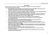
... Replace damaged test leads. • When using the Calibrator. See "Ex Hazardous Areas". • Replace the battery as soon as described in this User Manual and the Fluke 725Ex CCD (Concept Control Drawing) or the protection provided by the Calibrator may result in series with the circuit. 5 Ex... Hazardous Areas W Warning To avoid electric shock, injury, damage to the Calibrator, or ignition of an explosive ...
... Replace damaged test leads. • When using the Calibrator. See "Ex Hazardous Areas". • Replace the battery as soon as described in this User Manual and the Fluke 725Ex CCD (Concept Control Drawing) or the protection provided by the Calibrator may result in series with the circuit. 5 Ex... Hazardous Areas W Warning To avoid electric shock, injury, damage to the Calibrator, or ignition of an explosive ...

FE 725ex Users Manual
Page 16
...the measurement or sourcing application. 6 Confirm that all pressure connections are plugged into the current terminals. • Do not operate the Calibrator around explosive dust. • When using a pressure module, make sure the process pressure line is shut off and depressurized before ...When measuring the pressure of toxic or flammable gases, care must be taken to minimize the possibility of leakage. 725Ex Users Manual • When servicing the Calibrator, use , verify the Calibrator's operation by measuring a known voltage. • Never touch the probe to a voltage source when the ...
...the measurement or sourcing application. 6 Confirm that all pressure connections are plugged into the current terminals. • Do not operate the Calibrator around explosive dust. • When using a pressure module, make sure the process pressure line is shut off and depressurized before ...When measuring the pressure of toxic or flammable gases, care must be taken to minimize the possibility of leakage. 725Ex Users Manual • When servicing the Calibrator, use , verify the Calibrator's operation by measuring a known voltage. • Never touch the probe to a voltage source when the ...
FE 725ex Users Manual
Page 18
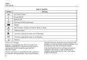
... "Ex Hazardous Areas". In case of the Calibrator in this manual. Battery Risk of the Calibrator invalidates its Ex Approval and may impair its safe operation in an Ex-hazardous area. Fully observe all instructions, warnings, and cautions contained in an Ex-hazardous area. 725Ex Users Manual Symbol F + J ( M W T ) Table 2. Double insulated Conforms to relevant European...
... "Ex Hazardous Areas". In case of the Calibrator in this manual. Battery Risk of the Calibrator invalidates its Ex Approval and may impair its safe operation in an Ex-hazardous area. Fully observe all instructions, warnings, and cautions contained in an Ex-hazardous area. 725Ex Users Manual Symbol F + J ( M W T ) Table 2. Double insulated Conforms to relevant European...

FE 725ex Users Manual
Page 20
725Ex Users Manual Certification Information • P ( II 1 G EEx ia IIB 171 °C 0344 KEMA 04ATEX1303X • ) Class I Div. 1 Groups B,C, and D LR110460 Class I Div 1, Groups B,C,D RECALL Hz ˚C &#... Martel Electronics, Inc., 1F Commons Drive Londonderry, NH, USA Getting Acquainted with the Calibrator Input and Output Terminals Figure 2 shows the Calibrator input and output terminals. Input/Output Terminals and Connectors Table 3 explains their use. 10 1 725Ex MULTIFUNCTION PROCESS CALIBRATOR V mA LOOP ZERO MEAS SOURCE STORE SETUP V mA TC RTD 2004.1573266 LR110460...
725Ex Users Manual Certification Information • P ( II 1 G EEx ia IIB 171 °C 0344 KEMA 04ATEX1303X • ) Class I Div. 1 Groups B,C, and D LR110460 Class I Div 1, Groups B,C,D RECALL Hz ˚C &#... Martel Electronics, Inc., 1F Commons Drive Londonderry, NH, USA Getting Acquainted with the Calibrator Input and Output Terminals Figure 2 shows the Calibrator input and output terminals. Input/Output Terminals and Connectors Table 3 explains their use. 10 1 725Ex MULTIFUNCTION PROCESS CALIBRATOR V mA LOOP ZERO MEAS SOURCE STORE SETUP V mA TC RTD 2004.1573266 LR110460...

FE 725ex Users Manual
Page 22
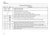
...: ANSCHLUSSSCHEMA BEACHTEN: SUIVRE LE SCHÉMA DE CONNEXION: FLUKE 725Ex CCD 0% 30V MAX ALL TERMINALS SOURCE / MEASURE mA+ 3W V TC Hz RTD MEASURE V mA LOOP mA- 4W COM COM Figure 3. 725Ex Users Manual Keys Figure 3 shows the Calibrator keys and Table 4 explains their use. 725Ex MULTIFUNCTION PROCESS CALIBRATOR 2 V mA LOOP ZERO MEAS V mA Hz 1 SOURCE STORE...
...: ANSCHLUSSSCHEMA BEACHTEN: SUIVRE LE SCHÉMA DE CONNEXION: FLUKE 725Ex CCD 0% 30V MAX ALL TERMINALS SOURCE / MEASURE mA+ 3W V TC Hz RTD MEASURE V mA LOOP mA- 4W COM COM Figure 3. 725Ex Users Manual Keys Figure 3 shows the Calibrator keys and Table 4 explains their use. 725Ex MULTIFUNCTION PROCESS CALIBRATOR 2 V mA LOOP ZERO MEAS V mA Hz 1 SOURCE STORE...
FE 725ex Users Manual
Page 24
725Ex Users Manual No. Retrieves a previous calibrator setup from a memory location. Toggles between voltage, mA sourcing, or mA simulate functions in the lower display. Repeated pushes cycle through MEASURE and SOURCE modes in lower display. Cycles the Calibrator through the RTD ...contrast. Saves Contrast Adjust setup. Repeated pushes cycle through the memory locations of calibrator setups. Repeated pushes cycle through the 2-, 3-, and 4-wire selections. Saves the Calibrator setup. Selects RTD (resistance temperature detector) measurement and sourcing function in the lower...
725Ex Users Manual No. Retrieves a previous calibrator setup from a memory location. Toggles between voltage, mA sourcing, or mA simulate functions in the lower display. Repeated pushes cycle through MEASURE and SOURCE modes in lower display. Cycles the Calibrator through the RTD ...contrast. Saves Contrast Adjust setup. Repeated pushes cycle through the memory locations of calibrator setups. Repeated pushes cycle through the 2-, 3-, and 4-wire selections. Saves the Calibrator setup. Selects RTD (resistance temperature detector) measurement and sourcing function in the lower...
FE 725ex Users Manual
Page 26
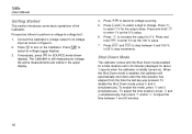
.... To enable the mode, press O and Z simultaneously. To adjust the time duration, press O and Z simultaneously, then press X and/or W to -voltage test: 1. Connect the Calibrator's voltage output to select dc voltage (upper display). Press l to its voltage input as follows to perform a voltage-to adjust the time between 0 and 100..., press for the output value. To disable the Shut Down mode, press O and Y simultaneously. When the Shut Down mode is still measuring dc voltage; 725Ex Users Manual Getting Started This section introduces some basic operations of the Calibrator.
.... To enable the mode, press O and Z simultaneously. To adjust the time duration, press O and Z simultaneously, then press X and/or W to -voltage test: 1. Connect the Calibrator's voltage output to select dc voltage (upper display). Press l to its voltage input as follows to perform a voltage-to adjust the time between 0 and 100..., press for the output value. To disable the Shut Down mode, press O and Y simultaneously. When the Shut Down mode is still measuring dc voltage; 725Ex Users Manual Getting Started This section introduces some basic operations of the Calibrator.

FE 725ex Users Manual
Page 28
725Ex Users Manual Contrast Adjustment To adjust the contrast, proceed as shown in Figure 6. 2. Press S to lighten contrast. 4. Press and hold Xto darken contrast. 3. Press and hold W to save the contrast level. 18 725Ex MULTIFUNCTION PROCESS CALIBRATOR 1 V mA LOOP ZERO 2 MEAS SOURCE V mA TC RTD Hz ˚C ˚F STORE SETUP RECALL 100% 25% 25% 4 0% 3 Figure 6. Adjusting the Contrast sh06f.eps Press C and O until Contst Adjust is displayed as follows: 1.
725Ex Users Manual Contrast Adjustment To adjust the contrast, proceed as shown in Figure 6. 2. Press S to lighten contrast. 4. Press and hold Xto darken contrast. 3. Press and hold W to save the contrast level. 18 725Ex MULTIFUNCTION PROCESS CALIBRATOR 1 V mA LOOP ZERO 2 MEAS SOURCE V mA TC RTD Hz ˚C ˚F STORE SETUP RECALL 100% 25% 25% 4 0% 3 Figure 6. Adjusting the Contrast sh06f.eps Press C and O until Contst Adjust is displayed as follows: 1.
FE 725ex Users Manual
Page 30
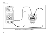
Connections for Supplying Loop Power 20 aly18f.eps Class I .S. Black Figure 8. 725Ex Users Manual 725Ex MULTIFUNCTION PROCESS CALIBRATOR V mA LOOP ZERO MEAS SOURCE STORE SETUP V mA TC RTD 2004.1573266 LR110460 Zone 0 AEx ia IIB 171 C I Div 1, Groups B,C,D RECALL Hz ˚C ˚F 100% 25% 25% 0% Red TEST DC PWR - ++ - +-
Connections for Supplying Loop Power 20 aly18f.eps Class I .S. Black Figure 8. 725Ex Users Manual 725Ex MULTIFUNCTION PROCESS CALIBRATOR V mA LOOP ZERO MEAS SOURCE STORE SETUP V mA TC RTD 2004.1573266 LR110460 Zone 0 AEx ia IIB 171 C I Div 1, Groups B,C,D RECALL Hz ˚C ˚F 100% 25% 25% 0% Red TEST DC PWR - ++ - +-
FE 725ex Users Manual
Page 32
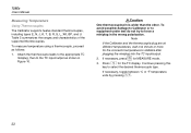
725Ex Users Manual Measuring Temperature Using Thermocouples The Calibrator supports twelve standard thermocouples, including types E, N, J, K, T, B, R, S, L, XK, BP, and U. If necessary, press for the connector temperature to force a miniplug in Figure 10. To measure temperature using a thermocouple, proceed as shown in the wrong polarization. Note If the Calibrator... by pressing D. 22 WCaution One thermocouple pin is wider than the other. To avoid possible damage to Calibrator or to equipment under test do not try to stabilize after plugging the miniplug into the TC input/output...
725Ex Users Manual Measuring Temperature Using Thermocouples The Calibrator supports twelve standard thermocouples, including types E, N, J, K, T, B, R, S, L, XK, BP, and U. If necessary, press for the connector temperature to force a miniplug in Figure 10. To measure temperature using a thermocouple, proceed as shown in the wrong polarization. Note If the Calibrator... by pressing D. 22 WCaution One thermocouple pin is wider than the other. To avoid possible damage to Calibrator or to equipment under test do not try to stabilize after plugging the miniplug into the TC input/output...

FE 725ex Users Manual
Page 40
Class I .S. Connections for Measuring Pressure aly37f.eps 30 725Ex Users Manual 725Ex MULTIFUNCTION PROCESS CALIBRATOR V mA LOOP ZERO MEAS SOURCE STORE SETUP V mA TC RTD 2004.1573266 LR110460 Zone 0 AEx ia IIB 171 C I Div 1, Groups B,C,D RECALL Hz ˚C ˚F 100% 25% 25% 0% Gage Module Isolation Valve Differential Module L H Tank Figure 13.
Class I .S. Connections for Measuring Pressure aly37f.eps 30 725Ex Users Manual 725Ex MULTIFUNCTION PROCESS CALIBRATOR V mA LOOP ZERO MEAS SOURCE STORE SETUP V mA TC RTD 2004.1573266 LR110460 Zone 0 AEx ia IIB 171 C I Div 1, Groups B,C,D RECALL Hz ˚C ˚F 100% 25% 25% 0% Gage Module Isolation Valve Differential Module L H Tank Figure 13.
FE 725ex Users Manual
Page 42
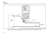
Refer to 20- Figure 14. mA Transmitter in an Ex hazardous area. Class I .S. Connections for Simulating a 4 to Fluke 725Ex CCD Control Drawing when using in a non-Ex hazardous Area aly17f.eps 32 725Ex Users Manual 725Ex MULTIFUNCTION PROCESS CALIBRATOR + Loop Power Supply Red V mA LOOP ZERO MEAS SOURCE STORE SETUP V mA TC RTD 2004.1573266 LR110460 Zone 0 AEx ia IIB 171 C I Div 1, Groups B,C,D RECALL Hz ˚C ˚F 100% 25% 25% 0% Black Readout or Controller -
Refer to 20- Figure 14. mA Transmitter in an Ex hazardous area. Class I .S. Connections for Simulating a 4 to Fluke 725Ex CCD Control Drawing when using in a non-Ex hazardous Area aly17f.eps 32 725Ex Users Manual 725Ex MULTIFUNCTION PROCESS CALIBRATOR + Loop Power Supply Red V mA LOOP ZERO MEAS SOURCE STORE SETUP V mA TC RTD 2004.1573266 LR110460 Zone 0 AEx ia IIB 171 C I Div 1, Groups B,C,D RECALL Hz ˚C ˚F 100% 25% 25% 0% Black Readout or Controller -
FE 725ex Users Manual
Page 62
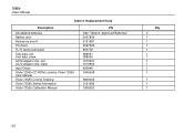
Replacement Parts Description AA alkaline batteries Battery door Accessory mount Tilt stand TL75 series test leads Test lead, red Test lead, black AC72 alligator clip, red AC72 alligator clip, black Input Decal Fluke 725Ex CD ROM, contains Fluke 725Ex User Manual Fluke 725Ex Control Drawing Fluke 725Ex Safety Information Fluke 725Ex Calibration Manual PN See "Table 8. Approved Batteries" 2097832 2151981 2097826 855742 688051 688066 1670641 1670652 690948 2406548 6800032 2151996 2406553 Qty. 4 1 1 1 1 1 1 1 1 1 1 1 1 1 52 725Ex Users Manual Table 9.
Replacement Parts Description AA alkaline batteries Battery door Accessory mount Tilt stand TL75 series test leads Test lead, red Test lead, black AC72 alligator clip, red AC72 alligator clip, black Input Decal Fluke 725Ex CD ROM, contains Fluke 725Ex User Manual Fluke 725Ex Control Drawing Fluke 725Ex Safety Information Fluke 725Ex Calibration Manual PN See "Table 8. Approved Batteries" 2097832 2151981 2097826 855742 688051 688066 1670641 1670652 690948 2406548 6800032 2151996 2406553 Qty. 4 1 1 1 1 1 1 1 1 1 1 1 1 1 52 725Ex Users Manual Table 9.


