Fluke 725 Process Calibrator Datasheet
Page 1
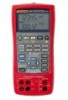
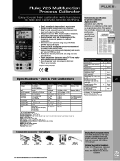
...; Ordering information Fluke-724 Temperature Calibrator (also see page 26) Fluke-725 Multifunction Process Calibrator Pt100 (392); Pt100, 200, 500, 1000 (385) Pressure2 (requires Fluke 700PXX Modules) M Frequency2; This application note helps interpret and compare performance specifications typically used test setups for later use • Easy-to-read measure/source screen lets you view input and output simultaneously • Measure volts, mA, RTDs, thermocouples, frequency, and...
...; Ordering information Fluke-724 Temperature Calibrator (also see page 26) Fluke-725 Multifunction Process Calibrator Pt100 (392); Pt100, 200, 500, 1000 (385) Pressure2 (requires Fluke 700PXX Modules) M Frequency2; This application note helps interpret and compare performance specifications typically used test setups for later use • Easy-to-read measure/source screen lets you view input and output simultaneously • Measure volts, mA, RTDs, thermocouples, frequency, and...

FE 725ex Users Manual
Page 2
..., to refund of the purchase price, free of charge repair, or replacement of a defective product which , in Fluke's opinion, has been misused, altered, neglected, contaminated, or damaged by use and service. Fluke authorized resellers shall extend this warranty on non-defective media. To obtain warranty service, contact your product online, visit register.fluke.com Fluke assumes no authority to extend a greater or...
..., to refund of the purchase price, free of charge repair, or replacement of a defective product which , in Fluke's opinion, has been misused, altered, neglected, contaminated, or damaged by use and service. Fluke authorized resellers shall extend this warranty on non-defective media. To obtain warranty service, contact your product online, visit register.fluke.com Fluke assumes no authority to extend a greater or...
FE 725ex Users Manual
Page 4
... RTDs ...34 Source Pressure Mode 37 Setting 0 % and 100 % Output Parameters 39 Stepping and Ramping the Output 39 Manually Stepping the mA Output 39 Auto Ramping the Output 40 Storing and Recalling Setups 40 Calibrating a Transmitter 41 Calibrating a Pressure Transmitter 43 Calibrating an I/P Device 45 Switch Test ...47 Testing an Output Device 48 Replacing the Batteries 49 Approved Batteries ...50 Maintenance ...50 Cleaning the Calibrator 50 ii to 20 mA...
... RTDs ...34 Source Pressure Mode 37 Setting 0 % and 100 % Output Parameters 39 Stepping and Ramping the Output 39 Manually Stepping the mA Output 39 Auto Ramping the Output 40 Storing and Recalling Setups 40 Calibrating a Transmitter 41 Calibrating a Pressure Transmitter 43 Calibrating an I/P Device 45 Switch Test ...47 Testing an Output Device 48 Replacing the Batteries 49 Approved Batteries ...50 Maintenance ...50 Cleaning the Calibrator 50 ii to 20 mA...
FE 725ex Users Manual
Page 5
Contents (continued) Service Center Calibration or Repair 50 Replacement Parts ...51 Accessories ...53 Specifications ...55 DC Voltage Measurement 55 DC Voltage Source...55 Millivolt Measurement and Source 55 DC mA Measurement and Source 56 Ohms Measurement 56 Ohms Source...56 Frequency Measurement 56 Frequency Source ...57 Temperature, Thermocouples 57 Loop Power Supply 57 RTD Excitation (simulation 58 Temperature, RTD Ranges, and Accuracies 58 Pressure Measurement 59 General Specifications 59 iii
Contents (continued) Service Center Calibration or Repair 50 Replacement Parts ...51 Accessories ...53 Specifications ...55 DC Voltage Measurement 55 DC Voltage Source...55 Millivolt Measurement and Source 55 DC mA Measurement and Source 56 Ohms Measurement 56 Ohms Source...56 Frequency Measurement 56 Frequency Source ...57 Temperature, Thermocouples 57 Loop Power Supply 57 RTD Excitation (simulation 58 Temperature, RTD Ranges, and Accuracies 58 Pressure Measurement 59 General Specifications 59 iii

FE 725ex Users Manual
Page 11
... Fluke To order accessories, receive operating assistance, or get the location of source and measurement functions, see Table 1. In addition to measure and source volts, current, pressure, resistance temperature detectors, thermocouples, frequency, and ohms. • Calibrates a transmitter using the Calibrator. To register this product, visit register.fluke.com 1 Multifunction Process Calibrator Introduction WWarning Read "Safety Information" before using the split-screen. • A thermocouple (TC) input/output...
... Fluke To order accessories, receive operating assistance, or get the location of source and measurement functions, see Table 1. In addition to measure and source volts, current, pressure, resistance temperature detectors, thermocouples, frequency, and ohms. • Calibrates a transmitter using the Calibrator. To register this product, visit register.fluke.com 1 Multifunction Process Calibrator Introduction WWarning Read "Safety Information" before using the split-screen. • A thermocouple (TC) input/output...
FE 725ex Users Manual
Page 13
... are suitably matched. The Model 725Ex Calibrator has been designed for use in Europe and as hazardous locations, see Replacement Parts in Table 9. • TL75 test leads (one set) • AC72 alligator clips (one set) • Stackable alligator clip test leads (one set) • Fluke 725Ex CD-ROM (contains Fluke 725Ex Users Manual) • Fluke 725Ex CCD • Fluke 725Ex Safety Information • 4 AA Batteries (installed) • Hex Key, 5/64 in., short arm...
... are suitably matched. The Model 725Ex Calibrator has been designed for use in Europe and as hazardous locations, see Replacement Parts in Table 9. • TL75 test leads (one set) • AC72 alligator clips (one set) • Stackable alligator clip test leads (one set) • Fluke 725Ex CD-ROM (contains Fluke 725Ex Users Manual) • Fluke 725Ex CCD • Fluke 725Ex Safety Information • 4 AA Batteries (installed) • Hex Key, 5/64 in., short arm...
FE 725ex Users Manual
Page 14
... the terminals connected to be the sum of the barrier Voc. This value will be determined using the ignition curves found in the circuit must exceed the Voc and Isc ratings for the specific terminals used. The Model 725Ex calibrator will be a source of terminals has a Voc and an Isc rating as transmitters and positioners (I/P devices). Again, Fluke 725Ex CCD...
... the terminals connected to be the sum of the barrier Voc. This value will be determined using the ignition curves found in the circuit must exceed the Voc and Isc ratings for the specific terminals used. The Model 725Ex calibrator will be a source of terminals has a Voc and an Isc rating as transmitters and positioners (I/P devices). Again, Fluke 725Ex CCD...
FE 725ex Users Manual
Page 15
...; Turn off circuit power before entering an Ex hazardous area or using the Calibrator. Opening the case invalidates the Calibrator's Ex Approval. • Make sure the battery door is closed and latched before connecting the Calibrator mA and COM terminals in the circuit. See "Ex Hazardous Areas". • Replace the battery as soon as described in this User Manual and the Fluke 725Ex CCD...
...; Turn off circuit power before entering an Ex hazardous area or using the Calibrator. Opening the case invalidates the Calibrator's Ex Approval. • Make sure the battery door is closed and latched before connecting the Calibrator mA and COM terminals in the circuit. See "Ex Hazardous Areas". • Replace the battery as soon as described in this User Manual and the Fluke 725Ex CCD...

FE 725ex Users Manual
Page 16
... be taken to minimize the possibility of leakage. Do not open the Calibrator case. Opening the case invalidates the Calibrator's Ex Approval. • Do not allow water inside the case. • Before each use only specified replacement parts. 725Ex Users Manual • When servicing the Calibrator, use , verify the Calibrator's operation by measuring a known voltage. • Never touch the probe to a voltage source...
... be taken to minimize the possibility of leakage. Do not open the Calibrator case. Opening the case invalidates the Calibrator's Ex Approval. • Do not allow water inside the case. • Before each use only specified replacement parts. 725Ex Users Manual • When servicing the Calibrator, use , verify the Calibrator's operation by measuring a known voltage. • Never touch the probe to a voltage source...
FE 725ex Users Manual
Page 19
... that the user observes and applies the requirements as stated in circuits with compatible entity parameters. When the calibrator is used in an Ex hazardous area, unless the area is avoided. • Use must be safe, do not connect to the specified application parameters. • Do not open the Calibrator. • Do not remove or install the batteries within...
... that the user observes and applies the requirements as stated in circuits with compatible entity parameters. When the calibrator is used in an Ex hazardous area, unless the area is avoided. • Use must be safe, do not connect to the specified application parameters. • Do not open the Calibrator. • Do not remove or install the batteries within...
FE 725ex Users Manual
Page 26
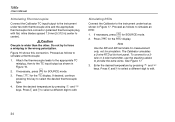
... voltage sourcing. 5. M 3. Shut Down Mode The calibrator comes with the Shut Down mode enabled for a time duration set to its voltage input as the 100 % value. 7. Connect the Calibrator's voltage output to 30 minutes (displayed for about 1 second when the calibrator is initially turned on the Calibrator. 725Ex Users Manual Getting Started This section introduces some basic operations of the Calibrator. When the Shut Down mode is still measuring dc...
... voltage sourcing. 5. M 3. Shut Down Mode The calibrator comes with the Shut Down mode enabled for a time duration set to its voltage input as the 100 % value. 7. Connect the Calibrator's voltage output to 30 minutes (displayed for about 1 second when the calibrator is initially turned on the Calibrator. 725Ex Users Manual Getting Started This section introduces some basic operations of the Calibrator. When the Shut Down mode is still measuring dc...
FE 725ex Users Manual
Page 29
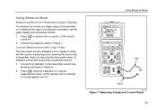
... l while the Calibrator is disconnected from plant wiring. Connect the leads as follows: 1. To measure current with the current measuring circuit, allowing the user to test a transmitter when it is in Figure 7. LOOP appears and an internal 12-V loop supply turns on . 2. Measuring Voltage and Current Output 19 Using Measure Mode 725Ex MULTIFUNCTION PROCESS CALIBRATOR V mA LOOP ZERO MEAS SOURCE STORE SETUP V mA...
... l while the Calibrator is disconnected from plant wiring. Connect the leads as follows: 1. To measure current with the current measuring circuit, allowing the user to test a transmitter when it is in Figure 7. LOOP appears and an internal 12-V loop supply turns on . 2. Measuring Voltage and Current Output 19 Using Measure Mode 725Ex MULTIFUNCTION PROCESS CALIBRATOR V mA LOOP ZERO MEAS SOURCE STORE SETUP V mA...

FE 725ex Users Manual
Page 38
... the pressure module fitting and connecting fittings or adapters. • To avoid damaging the pressure module from Fluke. Before using a pressure module, read its instruction sheet. To measure pressure, attach the appropriate pressure module for the process pressure to be tested Proceed as follows to the pressure line. 725Ex Users Manual Measuring Pressure Many ranges and types of the...
... the pressure module fitting and connecting fittings or adapters. • To avoid damaging the pressure module from Fluke. Before using a pressure module, read its instruction sheet. To measure pressure, attach the appropriate pressure module for the process pressure to be tested Proceed as follows to the pressure line. 725Ex Users Manual Measuring Pressure Many ranges and types of the...

FE 725ex Users Manual
Page 39
... the module is not rezeroed every time it is used. 29 Modules vary in the module's instruction sheet. • To avoid damaging the pressure module from corrosion, use it is accurately known. Press A. Using Measure Mode Zeroing with specified materials. To adjust the Calibrator reading, proceed as shown in Figure 13. The Calibrator stores and automatically reuses the zero...
... the module is not rezeroed every time it is used. 29 Modules vary in the module's instruction sheet. • To avoid damaging the pressure module from corrosion, use it is accurately known. Press A. Using Measure Mode Zeroing with specified materials. To adjust the Calibrator reading, proceed as shown in Figure 13. The Calibrator stores and automatically reuses the zero...
FE 725ex Users Manual
Page 41
... Volts, ohms, and frequency are also sourced and shown in place of a transmitter and supplies a known, settable test current. Press Y and Z to select a different digit to 20-mA Transmitter Simulate is connected into a loop in the lower display. supplies voltages, currents, frequencies, and resistances; Using Source Mode In SOURCE mode, the Calibrator generates calibrated signals for current and enter the desired current by pressing X and W keys.
... Volts, ohms, and frequency are also sourced and shown in place of a transmitter and supplies a known, settable test current. Press Y and Z to select a different digit to 20-mA Transmitter Simulate is connected into a loop in the lower display. supplies voltages, currents, frequencies, and resistances; Using Source Mode In SOURCE mode, the Calibrator generates calibrated signals for current and enter the desired current by pressing X and W keys.
FE 725ex Users Manual
Page 42
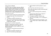
Refer to 20- Figure 14. Class I .S. Connections for Simulating a 4 to Fluke 725Ex CCD Control Drawing when using in a non-Ex hazardous Area aly17f.eps 32 mA Transmitter in an Ex hazardous area. 725Ex Users Manual 725Ex MULTIFUNCTION PROCESS CALIBRATOR + Loop Power Supply Red V mA LOOP ZERO MEAS SOURCE STORE SETUP V mA TC RTD 2004.1573266 LR110460 Zone 0 AEx ia IIB 171 C I Div 1, Groups B,C,D RECALL Hz ˚C ˚F 100% 25% 25% 0% Black Readout or Controller -
Refer to 20- Figure 14. Class I .S. Connections for Simulating a 4 to Fluke 725Ex CCD Control Drawing when using in a non-Ex hazardous Area aly17f.eps 32 mA Transmitter in an Ex hazardous area. 725Ex Users Manual 725Ex MULTIFUNCTION PROCESS CALIBRATOR + Loop Power Supply Red V mA LOOP ZERO MEAS SOURCE STORE SETUP V mA TC RTD 2004.1573266 LR110460 Zone 0 AEx ia IIB 171 C I Div 1, Groups B,C,D RECALL Hz ˚C ˚F 100% 25% 25% 0% Black Readout or Controller -
FE 725ex Users Manual
Page 44
725Ex Users Manual Simulating Thermocouples Connect the Calibrator TC input/output to the instrument under test as shown in the wrong polarization. WCaution One pin is wider than the other. Press T for SOURCE mode. 2. Enter the desired temperature by pressing X and W keys. See Figure 17. 3. Press Y and Z to select a different digit to simulate an RTD: M 1. If necessary, press for the TC display. The...
725Ex Users Manual Simulating Thermocouples Connect the Calibrator TC input/output to the instrument under test as shown in the wrong polarization. WCaution One pin is wider than the other. Press T for SOURCE mode. 2. Enter the desired temperature by pressing X and W keys. See Figure 17. 3. Press Y and Z to select a different digit to simulate an RTD: M 1. If necessary, press for the TC display. The...

FE 725ex Users Manual
Page 48
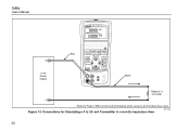
.... 2. The threads on the display. The Calibrator automatically senses which pressure module is attached and sets its range accordingly. 3. If desired, continue pressing U to change pressure display units to the Calibrator as shown on the pressure modules accept standard ¼ NPT pipe fittings. 725Ex Users Manual 1. Modules vary in the module's Instruction Sheet. Class I .S. Connections for Sourcing Pressure 38 Use the supplied ¼ NPT to...
.... 2. The threads on the display. The Calibrator automatically senses which pressure module is attached and sets its range accordingly. 3. If desired, continue pressing U to change pressure display units to the Calibrator as shown on the pressure modules accept standard ¼ NPT pipe fittings. 725Ex Users Manual 1. Modules vary in the module's Instruction Sheet. Class I .S. Connections for Sourcing Pressure 38 Use the supplied ¼ NPT to...

FE 725ex Users Manual
Page 50
... recall the settings for later use. An underscore appears below the selected memory location. 3. Press S until the memory number disappears then reappears. Steps are listed in a choice of the transmitter. In the display, the memory locations appear. 2. 725Ex Users Manual Auto Ramping the Output Auto ramping gives the ability to continuously apply a varying stimulus from the Calibrator to a transmitter, while your hands remain free to...
... recall the settings for later use. An underscore appears below the selected memory location. 3. Press S until the memory number disappears then reappears. Steps are listed in a choice of the transmitter. In the display, the memory locations appear. 2. 725Ex Users Manual Auto Ramping the Output Auto ramping gives the ability to continuously apply a varying stimulus from the Calibrator to a transmitter, while your hands remain free to...
FE 725ex Users Manual
Page 61
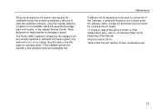
... an authorized service center or order replacement parts, refer to "Contacting Fluke" at no responsibility for repair. Pressure modules do not need to accompany the Calibrator unless the module is available. Replacement Parts Table 9 lists the part number of the manual. The Fluke 725Ex Calibrator covered by the warranty will be repaired and returned for warranty terms. If the warranty period has expired or the operating limits are...
... an authorized service center or order replacement parts, refer to "Contacting Fluke" at no responsibility for repair. Pressure modules do not need to accompany the Calibrator unless the module is available. Replacement Parts Table 9 lists the part number of the manual. The Fluke 725Ex Calibrator covered by the warranty will be repaired and returned for warranty terms. If the warranty period has expired or the operating limits are...


