Fluke 1503 Support and Manuals
Get Help and Manuals for this Fluke item
Fluke 1503 Videos

?????????? FLUKE 1503
Duration: :16
Total Views: 28
Duration: :16
Total Views: 28
Popular Fluke 1503 Manual Pages
Fluke 1503 and 1507 Insulation Tester Datasheet - Page 1

...IV 600 V overvoltage category rating for added user protection
• Remote probe, test leads, probes and alligator clips included with each tester
• Accepts optional Fluke TPAK magnetic hanging system to use. 1507/1503
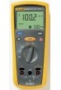
Insulation Testers
Technical Data
The Fluke 1507 and 1503 Insulation Testers are ideal for at least 1000 insulation tests
• One-year warranty With their multiple...
Fluke 1503 and 1507 Insulation Tester Datasheet - Page 5
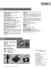
...remote probe
Ordering Information
Fluke-1507 Insulation Tester Fluke-1503 Insulation Tester
Included Remote probe, test leads, test probes, alligator clips, holster, user documentation
Optional accessories
TPAK™ C101 TLK225
Magnetic Tool Hanger Hard Case SureGrip Master Accessory Kit
TPAK
C101
5 Fluke Corporation 1507/1503 Insulation Testers
i1010-Kit
Fluke. Printed in L) Weight...
FE 1503-1507 Users Manual - Page 1

All rights reserved. ®
1507/1503 Insulation Testers Users Manual
June 2005
© 2005 Fluke Corporation. All product names are trademarks of their respective companies.
FE 1503-1507 Users Manual - Page 4

1507/1503
Users Manual
Testing the Batteries ...17 Testing the Fuse ...18 Replacing the Batteries and Fuse 19 Specifications...20
General Specifications 20 AC/DC Voltage Measurement 21 Earth-bond Resistance Measurement 22 Insulation Specifications 22
Model 1507 ...23 Model 1503 ...24 EN61557 Specification 24 Insulation Resistance Maximum and Minimum Display Values 26 Earth-Bond Resistance ...
FE 1503-1507 Users Manual - Page 9

...supply level (overhead or underground utility service).
CAT IV Testers are battery-powered insulation testers (hereafter, "the Tester"). These Testers meet CAT IV IEC 61010 standards. 1507/1503
Insulation Testers
Introduction
The Fluke model 1507 and model 1503 are designed to IV) based on the magnitude of model 1507. The Tester measures or tests the following:
• AC / DC Voltage...
FE 1503-1507 Users Manual - Page 10

... connecting Tester to circuit under test, or cause permanent loss of symbols used on the Tester, between the terminals or between
any terminal and earth ground. • Use caution with voltages above 30 V ac rms, 42 V ac peak, or 60 V dc. 1507/1503 Users Manual
Safety Information
Use the Tester only as specified in doubt, have the Tester serviced.
•...
FE 1503-1507 Users Manual - Page 12

... function (range, measurement units, modifiers, etc.). Figure 1. Rotary Switch
bbw03f.eps
4 The Tester comes out of a potentially hazardous voltage, when the Tester detects a voltage ≥ 30 V in insulation test, ≥ 2 V in Table 2.
The Tester presents a standard display for 10 minutes.
1507/1503 Users Manual
Unsafe Voltage
To alert you to the presence of Sleep mode when...
FE 1503-1507 Users Manual - Page 14

...button again to configure the Tester for insulation tests. The
backlight goes off . H
Turns the backlight on the display. The Z also appears
when insulation test is detected on the rotary
switch position) is active.
Indicates 30 V or
greater (ac or dc depending on the input.
Unsafe voltage warning. 1507/1503 Users Manual
Table 3.
L
Test lock.
When pressed before...
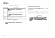
FE 1503-1507 Users Manual - Page 16

1507/1503 Users Manual
Table 4 Display Indicators (cont.)
Indicator P d
ZERO
VAC, VDC, Ω, kΩ, MΩ, GΩ
88.8.8 VDC 1888
COMPARE
t
Description Polarization index or dielectric absorption ratio test is selected Ohms lead zero is replaced. Calibrate the Tester.
8 Insulation test indicator. The Tester will not
operate at all until the battery is active.
Error ...
FE 1503-1507 Users Manual - Page 18
... live lead before testing.
10
when removing the test leads, remove the live lead;
Starts the Calibration mode. The Tester displays CAL and enters Calibration mode when the button is pressed. Power-Up Options
Button A L
Description
bswitch position turns on the following pages show how to the Tester, disconnect circuit power and discharge all LCD segments. 1507/1503 Users Manual...
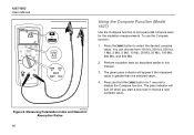
FE 1503-1507 Users Manual - Page 22

... switch to select polarization index or dielectric absorption ratio.
4. Measuring Insulation Resistance
14
Measuring Polarization Index and Dielectric Absorption Ratios (Model 1507)
Polarization Index (PI) is recommended.
2.
Insert test probes in the INSULATION and COM input terminals. 1507/1503 Users Manual
1507 INSULATION TESTER
bbw05f.eps
Figure 7.
Press the E button to the desired...
FE 1503-1507 Users Manual - Page 24
...Compare function. Perform insulation tests as described earlier in this manual.
3. The green pass indicator will turn off when you start a new test or choose a ...500 MΩ.
2. Press and hold the C button for the insulation measurements. 1507/1503 Users Manual
or
Using the Compare Function (Model 1507)
Use the Compare function to set a pass/fail compare level for 1 second to select the ...
FE 1503-1507 Users Manual - Page 25

The voltage function displays clear and the measured battery voltage is minimal battery life left. 1507 INSULATION TESTER
Insulation Testers Cleaning
Cleaning
Periodically wipe the case with no probes inserted.
2. Turn the rotary switch to initiate the fully loaded battery test. Do not use abrasives or solvents. Allow time for 2 seconds, the voltage display then returns.
Using the...
FE 1503-1507 Users Manual - Page 26

.... Press and hold T. 1507/1503 Users Manual
Testing the Fuse
XWWarning
To avoid electrical shock or injury, remove the test leads and any input signals before replacing the fuse. Turn the rotary switch to the O position.
2.
If the display reading is FUSE, the fuse is bad and should be replaced.
1507 INSULATION TESTER
315 mA
Fuse
OK
Figure 10. Replace the fuse as described below and...
FE 1503-1507 Users Manual - Page 36

1507/1503 Users Manual
Insulation Resistance Maximum and Minimum Display Values (cont.)
50 V
Limit Value
Minimum Display Value
100 V
Limit Value
Minimum Display Value
250 V
Limit Value
Minimum Display Value
...
Fluke 1503 Reviews
We have not received any reviews for Fluke yet.