Fluke 51II, 52II, 53II, and 54II Thermometer Datasheet
Page 1
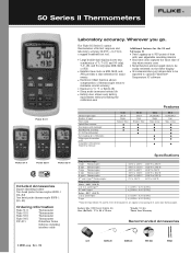
...; ● ● 54 II J,K,T,E,N,R,S Dual Time of Day ● Fluke 51 II Fluke 52 II Fluke 53 II Included Accessories Impact absorbing holster Two bead probe thermocouples 80PK-1 (54+52) One bead probe thermocouple 80PK-1 (51+53) Ordering Information Fluke 51 II Thermometer Fluke 52 II Thermometer Fluke 53 II Thermometer Fluke 54 II Thermometer FVF-SC1 FlukeView Forms Software including interface...
...; ● ● 54 II J,K,T,E,N,R,S Dual Time of Day ● Fluke 51 II Fluke 52 II Fluke 53 II Included Accessories Impact absorbing holster Two bead probe thermocouples 80PK-1 (54+52) One bead probe thermocouple 80PK-1 (51+53) Ordering Information Fluke 51 II Thermometer Fluke 52 II Thermometer Fluke 53 II Thermometer Fluke 54 II Thermometer FVF-SC1 FlukeView Forms Software including interface...
FE 51 & 52 II Users Manual
Page 3
Table of Contents Title Page Introduction ...1 Contacting Fluke ...1 Getting Started...4 Components...5 Display Elements ...6 Buttons...7 Using the Thermometer 9 Changing Setup Options 9 Entering or Exiting Setup 9 Setup Options ...9 Changing a Setup Option 10 Measuring Temperatures 11 Connecting a Thermocouple 11 Displaying Temperatures 11 Holding the Displayed Readings 12 Viewing the MIN, MAX, and AVG Readings 12 Using the Offset to Adjust for Probe Errors 12 i
Table of Contents Title Page Introduction ...1 Contacting Fluke ...1 Getting Started...4 Components...5 Display Elements ...6 Buttons...7 Using the Thermometer 9 Changing Setup Options 9 Entering or Exiting Setup 9 Setup Options ...9 Changing a Setup Option 10 Measuring Temperatures 11 Connecting a Thermocouple 11 Displaying Temperatures 11 Holding the Displayed Readings 12 Viewing the MIN, MAX, and AVG Readings 12 Using the Offset to Adjust for Probe Errors 12 i
FE 51 & 52 II Users Manual
Page 4
51 & 52 Series II Users Manual Maintenance...13 Replacing the Batteries 13 Cleaning the Case and Holster 13 Calibration ...13 Specifications ...13 Environmental...13 General...14 80 PK-1 Thermocouple (supplied with thermometer 14 Electrical...14 Replacement Parts and Accessories 15 ii
51 & 52 Series II Users Manual Maintenance...13 Replacing the Batteries 13 Cleaning the Case and Holster 13 Calibration ...13 Specifications ...13 Environmental...13 General...14 80 PK-1 Thermocouple (supplied with thermometer 14 Electrical...14 Replacement Parts and Accessories 15 ii
FE 51 & 52 II Users Manual
Page 5
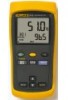
... countries Address correspondence to safety information in Table 1 and meter symbols in this manual. 51 & 52 Series II Introduction The Fluke Model 51 and Model 52 Thermometers ("the thermometer") are microprocessor-based, digital thermometers designed to use external J-, K-, T-, and Etype thermocouples (temperature probes) as specified in Table 2. Use the thermometer only as temperature sensors.
... countries Address correspondence to safety information in Table 1 and meter symbols in this manual. 51 & 52 Series II Introduction The Fluke Model 51 and Model 52 Thermometers ("the thermometer") are microprocessor-based, digital thermometers designed to use external J-, K-, T-, and Etype thermocouples (temperature probes) as specified in Table 2. Use the thermometer only as temperature sensors.
FE 51 & 52 II Users Manual
Page 6
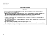
51 & 52 Series II Users Manual Table 1. Look for cracks or missing plastic. ...thermometer serviced. • Do not operate the thermometer around the connectors. • Disconnect the thermocouple(s) from the thermometer before opening the case. • Replace the batteries as soon as marked on the thermometer, between... the thermocouple(s), or between any thermocouple and earth ground. 2 Safety Information WWarning A Warning identifies conditions and actions that pose hazards to the ...
51 & 52 Series II Users Manual Table 1. Look for cracks or missing plastic. ...thermometer serviced. • Do not operate the thermometer around the connectors. • Disconnect the thermocouple(s) from the thermometer before opening the case. • Replace the batteries as soon as marked on the thermometer, between... the thermocouple(s), or between any thermocouple and earth ground. 2 Safety Information WWarning A Warning identifies conditions and actions that pose hazards to the ...
FE 51 & 52 II Users Manual
Page 7
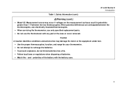
....) WWarning (cont.) • Model 52: Measurement errors may damage the meter or the equipment under test. • Use the proper thermocouples, function, and range for your thermometer. • Do not attempt to recharge the batteries. • To prevent explosion, do not ...identifies conditions and actions that may occur if voltages on the measurement surfaces result in potentials greater than 1 V between the thermocouples, use electrically insulated thermocouples. • When servicing the thermometer, use only specified replacement parts. • Do not use the thermometer with any part...
....) WWarning (cont.) • Model 52: Measurement errors may damage the meter or the equipment under test. • Use the proper thermocouples, function, and range for your thermometer. • Do not attempt to recharge the batteries. • To prevent explosion, do not ...identifies conditions and actions that may occur if voltages on the measurement surfaces result in potentials greater than 1 V between the thermocouples, use electrically insulated thermocouples. • When servicing the thermometer, use only specified replacement parts. • Do not use the thermometer with any part...
FE 51 & 52 II Users Manual
Page 9
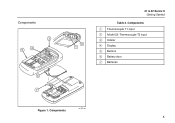
Components A Thermocouple T1 input B Model 52: Thermocouple T2 input C Holster D Display E Buttons F Battery door G Batteries Figure 1. Components aas01f.eps 5 Components 3 4 5 6 7 xx 2 1 51 & 52 Series II Getting Started Table 3.
Components A Thermocouple T1 input B Model 52: Thermocouple T2 input C Holster D Display E Buttons F Battery door G Batteries Figure 1. Components aas01f.eps 5 Components 3 4 5 6 7 xx 2 1 51 & 52 Series II Getting Started Table 3.
FE 51 & 52 II Users Manual
Page 10
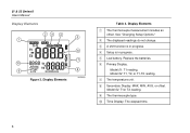
.... Model 52: T1or T2 reading. B The displayed readings do not change. I The thermocouple type. See "Changing Setup Options." E Low battery. Model 51: T1 reading. G The temperature unit. H Secondary Display: MAX, MIN, AVG, or offset. Display Elements A The thermocouple measurement includes an offset. 51 & 52 Series II Users Manual Display Elements 23 4 1 10 9 Figure 2. J Time...
.... Model 52: T1or T2 reading. B The displayed readings do not change. I The thermocouple type. See "Changing Setup Options." E Low battery. Model 51: T1 reading. G The temperature unit. H Secondary Display: MAX, MIN, AVG, or offset. Display Elements A The thermocouple measurement includes an offset. 51 & 52 Series II Users Manual Display Elements 23 4 1 10 9 Figure 2. J Time...
FE 51 & 52 II Users Manual
Page 13
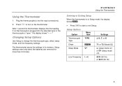
...or T2 (Model 52) Sleep Mode SLP on (sleep mode on the thermometer. After 1 second the thermometer displays the first reading. If no thermocouple is plugged into the input connector(s). 2. The thermometer stores the settings in Setup mode, the display shows s. • Press D to start ...or exit Setup. Press A to change the thermocouple type, offset, sleep mode, and line frequency settings. Setup settings reset only when the batteries are removed for more than 2 minutes. 51 & 52 Series II Using the Thermometer Entering or Exiting Setup When the thermometer...
...or T2 (Model 52) Sleep Mode SLP on (sleep mode on the thermometer. After 1 second the thermometer displays the first reading. If no thermocouple is plugged into the input connector(s). 2. The thermometer stores the settings in Setup mode, the display shows s. • Press D to start ...or exit Setup. Press A to change the thermocouple type, offset, sleep mode, and line frequency settings. Setup settings reset only when the batteries are removed for more than 2 minutes. 51 & 52 Series II Using the Thermometer Entering or Exiting Setup When the thermometer...
FE 51 & 52 II Users Manual
Page 14
Press K or N until the setting you want to change. 2. Notes Setup is automatically disabled in MIN MAX mode. 51 & 52 Series II Users Manual Changing a Setup Option 1. Offset: The primary display shows the temperature plus the offset and the secondary display shows the offset.... Sleep mode becomes enabled each time you want to indicate that you turn on the display. 4. Press E to change the thermocouple type. Model 52: You can store individual offsets for the local line frequency. 10 Remember to reset the offset to 0.0 when it to use appears...
Press K or N until the setting you want to change. 2. Notes Setup is automatically disabled in MIN MAX mode. 51 & 52 Series II Users Manual Changing a Setup Option 1. Offset: The primary display shows the temperature plus the offset and the secondary display shows the offset.... Sleep mode becomes enabled each time you want to indicate that you turn on the display. 4. Press E to change the thermocouple type. Model 52: You can store individual offsets for the local line frequency. 10 Remember to reset the offset to 0.0 when it to use appears...
FE 51 & 52 II Users Manual
Page 15
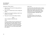
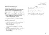
...or secondary display. 51 & 52 Series II Measuring Temperatures Notes The display shows "- - - -" when a thermocouple is correct.) 2. Displaying Temperatures 1. Hold or attach the thermocouple(s) to select the correct temperature scale. 2. Measuring Temperatures Connecting a Thermocouple To change the thermocouple type, see "... the temperature being measured is connected, the T2 reading appears in the primary display. Model 52: If only thermocouple T2 is outside the thermocouple's valid range. The North American ANSI Color Code is: Type J K E T N Color Black Yellow Purple...
...or secondary display. 51 & 52 Series II Measuring Temperatures Notes The display shows "- - - -" when a thermocouple is correct.) 2. Displaying Temperatures 1. Hold or attach the thermocouple(s) to select the correct temperature scale. 2. Measuring Temperatures Connecting a Thermocouple To change the thermocouple type, see "... the temperature being measured is connected, the T2 reading appears in the primary display. Model 52: If only thermocouple T2 is outside the thermocouple's valid range. The North American ANSI Color Code is: Type J K E T N Color Black Yellow Purple...
FE 51 & 52 II Users Manual
Page 16
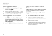
...mode, or the time at which the minimum or maximum occurred, appears on the display. Plug the thermocouple into the input connector. 2. Model 52: Press T to toggle showing the T1, T2, or ...display. 2. The allowable adjustment range is ± 5.0 oC or K, and ± 9.0 oF. 1. Place the thermocouple in a known, stable temperature environment (such as an ice bath or a dry well calibrator). 3. In Setup change ... Options.") 12 Press h to Adjust for the errors of a specific thermocouple. Press M to turn off the HOLD function. Press G, M (CANCEL) to stabilize. 4. Allow the readings to...
...mode, or the time at which the minimum or maximum occurred, appears on the display. Plug the thermocouple into the input connector. 2. Model 52: Press T to toggle showing the T1, T2, or ...display. 2. The allowable adjustment range is ± 5.0 oC or K, and ± 9.0 oF. 1. Place the thermocouple in a known, stable temperature environment (such as an ice bath or a dry well calibrator). 3. In Setup change ... Options.") 12 Press h to Adjust for the errors of a specific thermocouple. Press M to turn off the HOLD function. Press G, M (CANCEL) to stabilize. 4. Allow the readings to...
FE 51 & 52 II Users Manual
Page 18
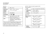
Equipment of OVERVOLTAGE CATEGORY I , Pollution Degree 2 per IEC1010-1* * Refers to the level of Impulse Withstand Voltage protection provided. 51 & 52 Series II Users Manual General Weight 280 g (10 oz) Dimensions (without holster) 2.8 cm × 7.8 cm × 16.2 cm (1.1 in × 3 ...circuits in which measures are taken to limit the transient over voltages to an appropriate low level. Example include protect electronic circuits. 80 PK-1 Thermocouple (supplied with thermometer) Type Temperature Range Accuracy Type K, Chromel Alumel, bead style −40 oC to +260 oC (−40 oF to...
Equipment of OVERVOLTAGE CATEGORY I , Pollution Degree 2 per IEC1010-1* * Refers to the level of Impulse Withstand Voltage protection provided. 51 & 52 Series II Users Manual General Weight 280 g (10 oz) Dimensions (without holster) 2.8 cm × 7.8 cm × 16.2 cm (1.1 in × 3 ...circuits in which measures are taken to limit the transient over voltages to an appropriate low level. Example include protect electronic circuits. 80 PK-1 Thermocouple (supplied with thermometer) Type Temperature Range Accuracy Type K, Chromel Alumel, bead style −40 oC to +260 oC (−40 oF to...
FE 51 & 52 II Users Manual
Page 19
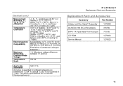
The above specifications do not include thermocouple error. 51 & 52 Series II Replacement Parts and Accessories Replacement Parts and Accessories Accessory Part Number Holster and Flex Stand™ Assembly 1272438 AA NEDA 15A IEC LR6 batteries 376756 80PK-1 K-Type Bead Thermocouple 773135 CD-ROM 1276106 Service Manual 1276123 15 and 0.08 % of reading for...
The above specifications do not include thermocouple error. 51 & 52 Series II Replacement Parts and Accessories Replacement Parts and Accessories Accessory Part Number Holster and Flex Stand™ Assembly 1272438 AA NEDA 15A IEC LR6 batteries 376756 80PK-1 K-Type Bead Thermocouple 773135 CD-ROM 1276106 Service Manual 1276123 15 and 0.08 % of reading for...