
Manual
Page 3
... apply to fuses, disposable batteries or to the Buyer transportation prepaid and the Buyer will be billed for Fluke products online at Fluke's option, to refund of the purchase price, free of charge repair, or replacement of a defective product which , in transit. Fluke warrants that software will be free from defects in material and workmanship under normal use and service. Warranty support is available...
... apply to fuses, disposable batteries or to the Buyer transportation prepaid and the Buyer will be billed for Fluke products online at Fluke's option, to refund of the purchase price, free of charge repair, or replacement of a defective product which , in transit. Fluke warrants that software will be free from defects in material and workmanship under normal use and service. Warranty support is available...

Manual
Page 5
Table of Contents Chapter Title Page Introduction...1 Unpacking the Test Tool Kit 2 Safety Information: Read First 5 Safe Use of Li-ion battery pack 9 1 Using the Scope and Meter 11 Powering the Test Tool 11 Resetting the Test Tool 12 Navigating a Menu ...13 Hiding Key Labels and Menus 14 Key Illumination...14 Input Connections ...15 Making Input Connections 15 Adjusting the Probe Type Settings 16 Selecting an Input Channel 17 i MyFlukeStore Shop for Fluke products online at: www. .com 1.877.766.5412
Table of Contents Chapter Title Page Introduction...1 Unpacking the Test Tool Kit 2 Safety Information: Read First 5 Safe Use of Li-ion battery pack 9 1 Using the Scope and Meter 11 Powering the Test Tool 11 Resetting the Test Tool 12 Navigating a Menu ...13 Hiding Key Labels and Menus 14 Key Illumination...14 Input Connections ...15 Making Input Connections 15 Adjusting the Probe Type Settings 16 Selecting an Input Channel 17 i MyFlukeStore Shop for Fluke products online at: www. .com 1.877.766.5412

Manual
Page 11
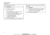
... 6 for mounting instructions) 3 Power Adapter (country dependent) 4 USB interface cable for PC connection (USB-A to mini-USB-B) 5 Safety Information sheet + CD ROM with Users Manual (multi-language) and FlukeView ScopeMeter Software for Windows demo package (with restricted functionality) 6 Shipment box (basic version only) Unpacking the Test Tool Kit The Fluke 190-062, 190-102, 190-104, 190-202 and 190-204 include also: # Description 7 Voltage Probe Set (red) 8 Voltage Probe Set (blue) 9 Voltage Probe Set (gray...
... 6 for mounting instructions) 3 Power Adapter (country dependent) 4 USB interface cable for PC connection (USB-A to mini-USB-B) 5 Safety Information sheet + CD ROM with Users Manual (multi-language) and FlukeView ScopeMeter Software for Windows demo package (with restricted functionality) 6 Shipment box (basic version only) Unpacking the Test Tool Kit The Fluke 190-062, 190-102, 190-104, 190-202 and 190-204 include also: # Description 7 Voltage Probe Set (red) 8 Voltage Probe Set (blue) 9 Voltage Probe Set (gray...
Manual
Page 12
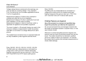
Fluke 190 Series II Users Manual The Fluke 190-502 includes also: # Description 11 Voltage Probe Set (red) 12 Voltage Probe Set (blue) Each set includes: a) 10:1 Voltage Probe, 500 MHz (red or blue) b) Hook Clip for Probe Tip (black ) c) Ground Lead with test pins (one red, one black). Fluke 190-xxx /S versions include also the following items (SCC290 kit): # Description 14 FlukeView ScopeMeter Software for Windows activation key (converts FlukeView DEMO status into full operational status...
Fluke 190 Series II Users Manual The Fluke 190-502 includes also: # Description 11 Voltage Probe Set (red) 12 Voltage Probe Set (blue) Each set includes: a) 10:1 Voltage Probe, 500 MHz (red or blue) b) Hook Clip for Probe Tip (black ) c) Ground Lead with test pins (one red, one black). Fluke 190-xxx /S versions include also the following items (SCC290 kit): # Description 14 FlukeView ScopeMeter Software for Windows activation key (converts FlukeView DEMO status into full operational status...
Manual
Page 16
... for "working voltage". The isolated input connectors have no exposed metal and are damaged. Whenever it is applicable for isolated (electrically floating) measurements and are used in this manual to indicate a measurement in a manner not specified may impair the protection provided by the equipment. Fluke 190-062, 190-102, 190-104, 190-202, 190-204: The BNC jacks can independently be connected to...
... for "working voltage". The isolated input connectors have no exposed metal and are damaged. Whenever it is applicable for isolated (electrically floating) measurements and are used in this manual to indicate a measurement in a manner not specified may impair the protection provided by the equipment. Fluke 190-062, 190-102, 190-104, 190-202, 190-204: The BNC jacks can independently be connected to...

Manual
Page 22
... update. 14 MyFlukeStore Shop for Fluke products online at any time: CLEAR Hide any key label, press again to the illuminated channel key(s). Off: - To display menus or key labels, press one of the LED function see the table below. the SCOPE key. See Chapter 6 'Tips' section 'Setting the Display AUTO-Off timer '. Fluke 190 Series II Users Manual Hiding Key Labels and Menus You can also close a menu or...
... update. 14 MyFlukeStore Shop for Fluke products online at any time: CLEAR Hide any key label, press again to the illuminated channel key(s). Off: - To display menus or key labels, press one of the LED function see the table below. the SCOPE key. See Chapter 6 'Tips' section 'Setting the Display AUTO-Off timer '. Fluke 190 Series II Users Manual Hiding Key Labels and Menus You can also close a menu or...
Manual
Page 26
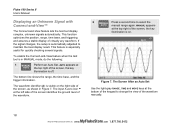
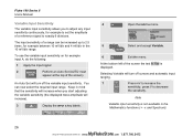
... . Fluke 190 Series II Users Manual Displaying an Unknown Signal with Connect-and-View™ The Connect-and-View feature lets the test tool display complex, unknown signals automatically. If the signal changes, the setup is on the right side of the screen, the key illumination is automatically adjusted to select the AUTO manual range again. AUTO appears at the top right of the screen, as shown in MANUAL mode, do the following: 1 MANUAL Perform an Auto Set...
... . Fluke 190 Series II Users Manual Displaying an Unknown Signal with Connect-and-View™ The Connect-and-View feature lets the test tool display complex, unknown signals automatically. If the signal changes, the setup is on the right side of the screen, the key illumination is automatically adjusted to select the AUTO manual range again. AUTO appears at the top right of the screen, as shown in MANUAL mode, do the following: 1 MANUAL Perform an Auto Set...
Manual
Page 34
... can be increased up to 2.5 times, for Fluke products online at the top of a reference signal to decrease V the sensitivity. Fluke 190 Series II Users Manual Variable Input Sensitivity The variable input sensitivity allows you start adjusting the variable sensitivity (the displayed trace amplitude will increase). 3 A Display the INPUT A key labels. 4 F4 Open the INPUT A menu. 5 Select and accept Variable. The input sensitivity of the screen the text A Var is...
... can be increased up to 2.5 times, for Fluke products online at the top of a reference signal to decrease V the sensitivity. Fluke 190 Series II Users Manual Variable Input Sensitivity The variable input sensitivity allows you start adjusting the variable sensitivity (the displayed trace amplitude will increase). 3 A Display the INPUT A key labels. 4 F4 Open the INPUT A menu. 5 Select and accept Variable. The input sensitivity of the screen the text A Var is...

Manual
Page 72
.... 1 Supply a signal to display waveforms on inputs A and B while triggering on Edges example. From this example you want to the red and black 4-mm banana jack inputs. Observe that the key labels at : www. .com 1.877.766.5412 To choose the external signal as trigger source, continue as follows: 2 TRIGGER Display the TRIGGER (On Edges) key labels. Fluke 190 series II Users Manual Triggering on External Waveforms (models 190-xx2) Use external...
.... 1 Supply a signal to display waveforms on inputs A and B while triggering on Edges example. From this example you want to the red and black 4-mm banana jack inputs. Observe that the key labels at : www. .com 1.877.766.5412 To choose the external signal as trigger source, continue as follows: 2 TRIGGER Display the TRIGGER (On Edges) key labels. Fluke 190 series II Users Manual Triggering on External Waveforms (models 190-xx2) Use external...
Manual
Page 84
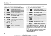
... selected screen+setup. Fluke 190 series II Users Manual Deleting Screens with Associated Setups To recall a screen+setup, do the following : 1 Display the SAVE key labels. From this point you can use cursors and zoom for analysis or you can print the recalled screen. Observe that the recalled waveform is displayed and that HOLD appears on the screen. SAVE Recalling Screens with Associated Setups To delete a screen and associated setup...
... selected screen+setup. Fluke 190 series II Users Manual Deleting Screens with Associated Setups To recall a screen+setup, do the following : 1 Display the SAVE key labels. From this point you can use cursors and zoom for analysis or you can print the recalled screen. Observe that the recalled waveform is displayed and that HOLD appears on the screen. SAVE Recalling Screens with Associated Setups To delete a screen and associated setup...

Manual
Page 100
The Display Auto-Off timer starts again and the display will be instructed to > 15 Hz, the Connect-andView function responds more quickly. Fluke 190 Series II Users Manual To turn on the display again do one of the following: • Press any key. ENTER If the frequency range is set ) key. 1 USER Display the USER key labels. 2 F1 Open the USER OPTIONS menu. 3 Open the AUTO SET ADJUST menu. the Auto-Off timer is instructed not to analyze low frequency signal components. Changing the Auto Set Options...
The Display Auto-Off timer starts again and the display will be instructed to > 15 Hz, the Connect-andView function responds more quickly. Fluke 190 Series II Users Manual To turn on the display again do one of the following: • Press any key. ENTER If the frequency range is set ) key. 1 USER Display the USER key labels. 2 F1 Open the USER OPTIONS menu. 3 Open the AUTO SET ADJUST menu. the Auto-Off timer is instructed not to analyze low frequency signal components. Changing the Auto Set Options...
Manual
Page 113
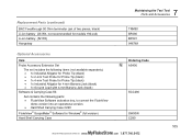
Replacement Parts (continued) BNC Feedthrough 50 Ohm terminator (set of two pieces, black) Li-ion battery (26 Wh, not recommended for models 190-xx4) Li-ion battery (52 Wh) Hangstrap 7 Maintaining the Test Tool Parts and Accessories TRM50 BP290 BP291 946769 Optional Accessories Item Probe Accessory Extension Set The set includes the following parts: • FlukeView Software activation key, to convert the FlukeView demo version into an operational version...
Replacement Parts (continued) BNC Feedthrough 50 Ohm terminator (set of two pieces, black) Li-ion battery (26 Wh, not recommended for models 190-xx4) Li-ion battery (52 Wh) Hangstrap 7 Maintaining the Test Tool Parts and Accessories TRM50 BP290 BP291 946769 Optional Accessories Item Probe Accessory Extension Set The set includes the following parts: • FlukeView Software activation key, to convert the FlukeView demo version into an operational version...

Manual
Page 115
... empty and must be empty. Troubleshooting The Test Tool Shuts Down After a Short Time • The batteries may be charged. A symbol indicates that the USB driver has been correctly installed, see Chapter 6 'Setting the Display AUTO-off ' timer), or connect the BC190 power adapter. To turn the display on press any key (restarts the 'display AUTO-off' timer), or connect the BC190 power adapter. • The power down timer is still on . The Test...
... empty and must be empty. Troubleshooting The Test Tool Shuts Down After a Short Time • The batteries may be charged. A symbol indicates that the USB driver has been correctly installed, see Chapter 6 'Setting the Display AUTO-off ' timer), or connect the BC190 power adapter. To turn the display on press any key (restarts the 'display AUTO-off' timer), or connect the BC190 power adapter. • The power down timer is still on . The Test...
Manual
Page 142
... 190-104, 33, 35 190-204, 33 Recalibrating, 101 Recalling Screens, 76 Recalling Setups, 77 Record Length, 111 Record+Setup Memory, 75 Recorder, 120 Recorder Options, 44 Recording Waveforms, 45 Reference value, 35, 40 Reference waveform, 30 Relative Measurements 104, 204, 34 Relative Meter Measurements 062, 102, 202, 39 Renaming files, 78 Replaceable Parts, 102 Replacement Set, 103, 104 Replacing Batteries, 97 Replay, 49, 75, 121 Reset, 12 Resetting...
... 190-104, 33, 35 190-204, 33 Recalibrating, 101 Recalling Screens, 76 Recalling Setups, 77 Record Length, 111 Record+Setup Memory, 75 Recorder, 120 Recorder Options, 44 Recording Waveforms, 45 Reference value, 35, 40 Reference waveform, 30 Relative Measurements 104, 204, 34 Relative Meter Measurements 062, 102, 202, 39 Renaming files, 78 Replaceable Parts, 102 Replacement Set, 103, 104 Replacing Batteries, 97 Replay, 49, 75, 121 Reset, 12 Resetting...
Manual
Page 148
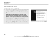
....766.5412 Depending on your PC settings, Windows may ask for the latest revision. It is advised to search the Windows Update Web site on the hard drive select "No, not this time". Fluke 190 Series II Users Manual Installing the USB Drivers To install the USB drivers, do the following: 1 Connect the Fluke 190 Series II instrument to power off. A-2 MyFlukeStore Shop for installing new hardware will open. When you have...
....766.5412 Depending on your PC settings, Windows may ask for the latest revision. It is advised to search the Windows Update Web site on the hard drive select "No, not this time". Fluke 190 Series II Users Manual Installing the USB Drivers To install the USB drivers, do the following: 1 Connect the Fluke 190 Series II instrument to power off. A-2 MyFlukeStore Shop for installing new hardware will open. When you have...

Datasheet
Page 2
...) Record length Time base range Maximum record length Timing accuracy Glitch capture Display and acquisition Display Display modes Visible screen width Digital persistence modes Waveform mathematics Acquisition modes Trigger and delay Source Modes Connect-and-View™ Video triggering (on 2ch) 1.25 GS/s for further details 8 bit ± (2.1 % of a trigger event; Includes field 1, field 2 and line select Non-interlaced video with automatic "Pass/Fail testing"; Replay Input A, B or External (via meter input) Input...
...) Record length Time base range Maximum record length Timing accuracy Glitch capture Display and acquisition Display Display modes Visible screen width Digital persistence modes Waveform mathematics Acquisition modes Trigger and delay Source Modes Connect-and-View™ Video triggering (on 2ch) 1.25 GS/s for further details 8 bit ± (2.1 % of a trigger event; Includes field 1, field 2 and line select Non-interlaced video with automatic "Pass/Fail testing"; Replay Input A, B or External (via meter input) Input...

Datasheet
Page 3
... specific user setup required. frequency and rms-value of additional sets on mathematical resultant waveform (excl. Each screen has date and time-stamp. Replay storage Two sets of screen events over and over time, between cursors Single vertical line Min-Max and Average voltage at any input waveform or on external flash memory drive through USB host port. When an anomaly is derived from full record...
... specific user setup required. frequency and rms-value of additional sets on mathematical resultant waveform (excl. Each screen has date and time-stamp. Replay storage Two sets of screen events over and over time, between cursors Single vertical line Min-Max and Average voltage at any input waveform or on external flash memory drive through USB host port. When an anomaly is derived from full record...

Datasheet
Page 5
... 30,000 data points, each holding min/max pair of information Min/max values Min/max values are created at samples that are measured at : www. .com 1.877.766.5412 ScopeMeter 190 Series II Fluke Corporation 5 Recorder modes 190-062 190-102 190-202 190-502 190-104 190-204 ScopeRecord™ Roll Mode Dual or multiple input waveform storage mode, using deep memory Source and display Input A, Input B, Dual. MyFlukeStore...
... 30,000 data points, each holding min/max pair of information Min/max values Min/max values are created at samples that are measured at : www. .com 1.877.766.5412 ScopeMeter 190 Series II Fluke Corporation 5 Recorder modes 190-062 190-102 190-202 190-502 190-104 190-204 ScopeRecord™ Roll Mode Dual or multiple input waveform storage mode, using deep memory Source and display Input A, Input B, Dual. MyFlukeStore...

Datasheet
Page 7
... operating altitude Maximum storage altitude Electro-MagneticCompatibility (EMC) Interfaces Probe calibration output Warranty Included accessories Battery charger/mains adapter Li-Ion battery pack Voltage probe sets. USB interface cable for left- Each set includes: Ground lead, hook clip, ground spring and probe tip insulation sleeve. Multi language users manuals on accessories BC190 BP290 (2400 mAh) VPS410 (one red, one blue) BP291 (4800 mAh) VPS410 (one red, one grey, one blue...
... operating altitude Maximum storage altitude Electro-MagneticCompatibility (EMC) Interfaces Probe calibration output Warranty Included accessories Battery charger/mains adapter Li-Ion battery pack Voltage probe sets. USB interface cable for left- Each set includes: Ground lead, hook clip, ground spring and probe tip insulation sleeve. Multi language users manuals on accessories BC190 BP290 (2400 mAh) VPS410 (one red, one blue) BP291 (4800 mAh) VPS410 (one red, one grey, one blue...
Datasheet
Page 8
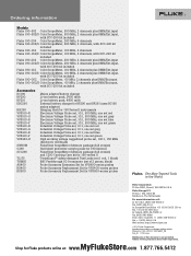
... 2 pieces, black) Probe Accessory Extension Set for VPS400-series probes Probe Accessory Replacement Set for VPS400-series probes Probe Accessory Replacement Set for VPS500-series probes Fluke. MyFlukeStore www. 8SFhluokepCfoorprorFatliuonke SpcoropedMuetcerts190oSnelriineseIIat: .com 1.877.766.5412 Ordering information Models Fluke 190-502 Color ScopeMeter, 500 MHz, 2 channels plus DMM/Ext.input Fluke 190-502/S Color ScopeMeter, 500 MHz, 2 channels plus DMM/Ext.input, with SCC-290 kit included Fluke 190-204 Color ScopeMeter, 200 MHz, 4 channels Fluke 190-204...
... 2 pieces, black) Probe Accessory Extension Set for VPS400-series probes Probe Accessory Replacement Set for VPS400-series probes Probe Accessory Replacement Set for VPS500-series probes Fluke. MyFlukeStore www. 8SFhluokepCfoorprorFatliuonke SpcoropedMuetcerts190oSnelriineseIIat: .com 1.877.766.5412 Ordering information Models Fluke 190-502 Color ScopeMeter, 500 MHz, 2 channels plus DMM/Ext.input Fluke 190-502/S Color ScopeMeter, 500 MHz, 2 channels plus DMM/Ext.input, with SCC-290 kit included Fluke 190-204 Color ScopeMeter, 200 MHz, 4 channels Fluke 190-204...


