
Fluke 73, 77, 175, 177, and 179 Digital Multimeter Datasheet
Page 1
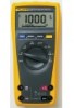
... 170 Series have significant improvements over Fluke's original 70 Series like true-rms, more information, go to view. Battery life: 200 hours typical for maintenance, field service and bench repair. Fluke 73, 77, 175, 177 and 179 Digital Multimeters Versatile meters for alkaline. Size (HxWxL): 4.3 cm x 9.0 cm x 18.5 cm (1.7 in x 3.5 in x 7.3 in) Limited lifetime warranty Recommended accessories - 70 and 170 Series DMMs...
... 170 Series have significant improvements over Fluke's original 70 Series like true-rms, more information, go to view. Battery life: 200 hours typical for maintenance, field service and bench repair. Fluke 73, 77, 175, 177 and 179 Digital Multimeters Versatile meters for alkaline. Size (HxWxL): 4.3 cm x 9.0 cm x 18.5 cm (1.7 in x 3.5 in x 7.3 in) Limited lifetime warranty Recommended accessories - 70 and 170 Series DMMs...

FE 175,177,179 Users Manual
Page 1
® Models 175, 177, 179 True RMS Multimeters Users Manual May 2003 (English) © 2003 Fluke Corporation. Printed in USA. All rights reserved.
® Models 175, 177, 179 True RMS Multimeters Users Manual May 2003 (English) © 2003 Fluke Corporation. Printed in USA. All rights reserved.
FE 175,177,179 Users Manual
Page 2
... defined as seven years after Fluke discontinues manufacturing the product, but the warranty period shall be free from defects in material and workmanship for its option, repair at no risk for product repaired or replaced in transit. If the product is held invalid or unenforceable by use outside of the product's specifications, or normal wear and tear...
... defined as seven years after Fluke discontinues manufacturing the product, but the warranty period shall be free from defects in material and workmanship for its option, repair at no risk for product repaired or replaced in transit. If the product is held invalid or unenforceable by use outside of the product's specifications, or normal wear and tear...

FE 175,177,179 Users Manual
Page 3
Table of Contents Title Page Contacting Fluke ...1 "Warning" and "Caution" Statements 1 Unsafe Voltage...1 Test Lead Alert ...1 Battery Saver ("Sleep Mode 2 Terminals ...2 Rotary Switch Positions...2 Display ...3 MIN MAX AVG Recording Mode 4 Display HOLD and AutoHOLD Modes 4 YELLOW Button ...4 Display Backlight (Model 177 and 179 Only 4 Manual Ranging and Autoranging 5 Power-Up Options ...5 Making Basic Measurements 6 Measuring AC and DC Voltage 6 Measuring Resistance ...6 Measuring Capacitance...6 Testing for Continuity...
Table of Contents Title Page Contacting Fluke ...1 "Warning" and "Caution" Statements 1 Unsafe Voltage...1 Test Lead Alert ...1 Battery Saver ("Sleep Mode 2 Terminals ...2 Rotary Switch Positions...2 Display ...3 MIN MAX AVG Recording Mode 4 Display HOLD and AutoHOLD Modes 4 YELLOW Button ...4 Display Backlight (Model 177 and 179 Only 4 Manual Ranging and Autoranging 5 Power-Up Options ...5 Making Basic Measurements 6 Measuring AC and DC Voltage 6 Measuring Resistance ...6 Measuring Capacitance...6 Testing for Continuity...
FE 175,177,179 Users Manual
Page 4
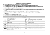
...) ii XW Warning. see manual b Battery (Low battery when shown on the Meter, between the terminals or between any terminal and earth ground. ⇒ Use caution with IEC 61010-1. 54CJ Conforms to European Union directives F B DC/AC Earth ground Canadian Standards Association T Double insulated Important Information; These voltages pose a shock hazard. ⇒ Replace the battery as soon as specified...
...) ii XW Warning. see manual b Battery (Low battery when shown on the Meter, between the terminals or between any terminal and earth ground. ⇒ Use caution with IEC 61010-1. 54CJ Conforms to European Union directives F B DC/AC Earth ground Canadian Standards Association T Double insulated Important Information; These voltages pose a shock hazard. ⇒ Replace the battery as soon as specified...

FE 175,177,179 Users Manual
Page 5
... Warning Attempting to or from the primary supply level (overhead or underground utility service). Test Lead Alert To remind you move the rotary switch to make a measurement with a 6000-count, 3 3/4-digit display and a bar graph. CAT III meters are in the correct terminals, LEAd is displayed. The Fluke Model 175, Model 177, and Model 179 are designed to protect against transients from...
... Warning Attempting to or from the primary supply level (overhead or underground utility service). Test Lead Alert To remind you move the rotary switch to make a measurement with a 6000-count, 3 3/4-digit display and a bar graph. CAT III meters are in the correct terminals, LEAd is displayed. The Fluke Model 175, Model 177, and Model 179 are designed to protect against transients from...

FE 175,177,179 Users Manual
Page 6
... 99.99 kHz. Models 175, 177 & 179 Users Manual Battery Saver ("Sleep Mode") The Meter enters the "Sleep mode" and blanks the display if there is displayed. Terminals . 1 3 V FUSED 2 4 Item 1 2 3 4 AIK01F.EPS Description Input terminal for 30 BA seconds maximum). Hz Frequency from 2 Hz to 10 A (20 A overload for 30 seconds maximum) >10.00 display flashes. >20 A, OL is no function change or button press for 2 minutes...
... 99.99 kHz. Models 175, 177 & 179 Users Manual Battery Saver ("Sleep Mode") The Meter enters the "Sleep mode" and blanks the display if there is displayed. Terminals . 1 3 V FUSED 2 4 Item 1 2 3 4 AIK01F.EPS Description Input terminal for 30 BA seconds maximum). Hz Frequency from 2 Hz to 10 A (20 A overload for 30 seconds maximum) >10.00 display flashes. >20 A, OL is no function change or button press for 2 minutes...

FE 175,177,179 Users Manual
Page 7
... units. Replace battery. 10 610000mV All possible ranges. 11 Bar graph Analog display. 12 Auto Range The Meter selects the range with the best resolution. bAtt diSC EEPr Err CAL Err Error Messages Replace the battery immediately. Display holds present reading until it detects new stable input. MIN MAX AVG enabled. Low battery. In the capacitance function, too much electrical charge is enabled. Calibrate Meter. 3 Display No. Manual Range The user selects...
... units. Replace battery. 10 610000mV All possible ranges. 11 Bar graph Analog display. 12 Auto Range The Meter selects the range with the best resolution. bAtt diSC EEPr Err CAL Err Error Messages Replace the battery immediately. Display holds present reading until it detects new stable input. MIN MAX AVG enabled. Low battery. In the capacitance function, too much electrical charge is enabled. Calibrate Meter. 3 Display No. Manual Range The user selects...

FE 175,177,179 Users Manual
Page 8
... switch setting, e.g., to select alternate measurement functions on and off after 2 minutes. 4 XW Display HOLD and AutoHOLD Modes Warning To avoid electric shock, do not use MIN MAX AVG recording: ⇒ Make sure that the Meter is in the desired measurement ⇒ mfunction and range. (Autoranging is the specified accuracy of all readings. Models 175, 177 & 179 Users Manual MIN MAX AVG Recording Mode...
... switch setting, e.g., to select alternate measurement functions on and off after 2 minutes. 4 XW Display HOLD and AutoHOLD Modes Warning To avoid electric shock, do not use MIN MAX AVG recording: ⇒ Make sure that the Meter is in the desired measurement ⇒ mfunction and range. (Autoranging is the specified accuracy of all readings. Models 175, 177 & 179 Users Manual MIN MAX AVG Recording Mode...

FE 175,177,179 Users Manual
Page 9
... Recording mode, or the AutoHOLD mode. Dampens display fluctuations of rapidly changing inputs by digital filtering. Sleep mode is also disabled while the Meter is turned OFF. Note You cannot manually change . 3. S Disables automatic 2-minute backlight timeout. (Model 177 and 179 Only) 5 the software version number is displayed. 2. To enter the Manual Range mode, press RANGE. After the highest range, the Meter wraps to Autorange and Auto Range is displayed. 1. Manual Range is displayed and the Meter resumes normal operation. Manual Ranging...
... Recording mode, or the AutoHOLD mode. Dampens display fluctuations of rapidly changing inputs by digital filtering. Sleep mode is also disabled while the Meter is turned OFF. Note You cannot manually change . 3. S Disables automatic 2-minute backlight timeout. (Model 177 and 179 Only) 5 the software version number is displayed. 2. To enter the Manual Range mode, press RANGE. After the highest range, the Meter wraps to Autorange and Auto Range is displayed. 1. Manual Range is displayed and the Meter resumes normal operation. Manual Ranging...

FE 175,177,179 Users Manual
Page 10
... HOLD MIN MAX RANGE Measuring Resistance HOLD MIN MAX RANGE Measuring Capacitance HOLD MIN MAX RANGE + _ + _ AIK03F.EPS + _ + 6 AIK04F.EPS AIK05F.EPS Warning To avoid electric shock, injury, or damage to make basic measurements. Models 175, 177 & 179 Users Manual Making Basic Measurements The figures on the following pages show how to the Meter, disconnect circuit power and discharge...
... HOLD MIN MAX RANGE Measuring Resistance HOLD MIN MAX RANGE Measuring Capacitance HOLD MIN MAX RANGE + _ + _ AIK03F.EPS + _ + 6 AIK04F.EPS AIK05F.EPS Warning To avoid electric shock, injury, or damage to make basic measurements. Models 175, 177 & 179 Users Manual Making Basic Measurements The figures on the following pages show how to the Meter, disconnect circuit power and discharge...

FE 175,177,179 Users Manual
Page 11
Testing for Continuity HOLD MINMAX RANGE HOLD MINMAX RANGE Testing Diodes Good Diode HOLD MINMAX RANGE Making Basic Measurements Good Diode HOLD MINMAX RANGE Measuring Temperature (Model 179 Only) AIK06F.EPS HOLD MINMAX RANGE RANGE Vent 80BK1 Type K Thermocouple or Pipe Probe XWWarning: Do not connect 80BK1 to live circuits. AIK10F.EPS + _ Single Beep Forward Bias Bad Diode HOLD MINMAX RANGE + _ Reverse Bias Bad Diode HOLD MINMAX RANGE CAT + _ Open + _ and Shorted AIK07F.EPS 7
Testing for Continuity HOLD MINMAX RANGE HOLD MINMAX RANGE Testing Diodes Good Diode HOLD MINMAX RANGE Making Basic Measurements Good Diode HOLD MINMAX RANGE Measuring Temperature (Model 179 Only) AIK06F.EPS HOLD MINMAX RANGE RANGE Vent 80BK1 Type K Thermocouple or Pipe Probe XWWarning: Do not connect 80BK1 to live circuits. AIK10F.EPS + _ Single Beep Forward Bias Bad Diode HOLD MINMAX RANGE + _ Reverse Bias Bad Diode HOLD MINMAX RANGE CAT + _ Open + _ and Shorted AIK07F.EPS 7

FE 175,177,179 Users Manual
Page 12
...digits that are displayed on a True RMS meter when the test leads are open -circuit potential to earth is why AC voltage and current ranges are specified from 5% of 60 mA AC, or 3 mA AC HOLD MINMAX RANGE DC mA + + A CAT CAT AIK08F.EPS 8 Unspecified input levels on . Models 175, 177 & 179 Users Manual...the Meter's fuses before testing. (See "Testing the Fuses".) • Use the proper terminals, switch position, and range for your measurement. • Never place the probes in -circuit current measure- Understanding AC Zero Input Behavior of True RMS Meters Unlike averaging meters, which...
...digits that are displayed on a True RMS meter when the test leads are open -circuit potential to earth is why AC voltage and current ranges are specified from 5% of 60 mA AC, or 3 mA AC HOLD MINMAX RANGE DC mA + + A CAT CAT AIK08F.EPS 8 Unspecified input levels on . Models 175, 177 & 179 Users Manual...the Meter's fuses before testing. (See "Testing the Fuses".) • Use the proper terminals, switch position, and range for your measurement. • Never place the probes in -circuit current measure- Understanding AC Zero Input Behavior of True RMS Meters Unlike averaging meters, which...

FE 175,177,179 Users Manual
Page 13
... ⇒ To exit frequency, press YELLOW button or turn the rotary switch. ⇒ In frequency, the bar graph shows the AC/DC voltage or AC current accurately up to 1 kHz. ⇒ Select progressively lower ranges using manual ranging for a stable reading. Because the bar graph updates about 40 times per second, which is 10 times faster than the digital display, the bar graph is...
... ⇒ To exit frequency, press YELLOW button or turn the rotary switch. ⇒ In frequency, the bar graph shows the AC/DC voltage or AC current accurately up to 1 kHz. ⇒ Select progressively lower ranges using manual ranging for a stable reading. Because the bar graph updates about 40 times per second, which is 10 times faster than the digital display, the bar graph is...

FE 175,177,179 Users Manual
Page 14
Models 175, 177 & 179 Users Manual Cleaning Wipe the case with a damp cloth and mild detergent. Dirt or moisture in the terminals can affect readings. HOLD MINMAX RANGE 440 mA 11 A Test fuses as shown below. Do not use abrasives or solvents. XW Testing the Fuses Warning To avoid electrical shock or injury, remove the test leads and any input signals before replacing the fuse.
Models 175, 177 & 179 Users Manual Cleaning Wipe the case with a damp cloth and mild detergent. Dirt or moisture in the terminals can affect readings. HOLD MINMAX RANGE 440 mA 11 A Test fuses as shown below. Do not use abrasives or solvents. XW Testing the Fuses Warning To avoid electrical shock or injury, remove the test leads and any input signals before replacing the fuse.

FE 175,177,179 Users Manual
Page 15
... Fuse Display: Digital: 6000 counts, updates 4/sec Bar Graph: 33 segments; Storage: 12,000 m Temperature: Operating: −10 °C to 1000 V Overvoltage Category III, 600 V Overvoltage P ; Accuracy specifications take the form of: ± ( [ % of Reading ] + [ Counts ] ) Maximum voltage between any terminal and earth ground: 1000 V DC or AC RMS Surge Protection: W Fuse for mA inputs: W Fuse for 1 yr after calibration...
... Fuse Display: Digital: 6000 counts, updates 4/sec Bar Graph: 33 segments; Storage: 12,000 m Temperature: Operating: −10 °C to 1000 V Overvoltage Category III, 600 V Overvoltage P ; Accuracy specifications take the form of: ± ( [ % of Reading ] + [ Counts ] ) Maximum voltage between any terminal and earth ground: 1000 V DC or AC RMS Surge Protection: W Fuse for mA inputs: W Fuse for 1 yr after calibration...

FE 175,177,179 Users Manual
Page 16
Models 175, 177 & 179 Users Manual Function Range 1 Resolution Accuracy ± ( [ % of 250 µs or longer. 0.9 % + 2 0.9 % + 1 0.9 % + 1 0.9 % + 1 0.9 % + 1 1.5 % + 3 0.9 % + 2 0.9 % + 1 0.9 % + 1 0.9 % + 1 0.9 % + 1 1.5 % + 3 0.9 % + 2 0.9 %...8486; 0.01 MΩ Meter beeps at < 25 Ω, beeper turns off at > 250 Ω; In the 9999 µF range for measurements to 1000 ...full scale up to 500 V, decreasing linearly to 3. 4. Crest factor of range. 2. Amps input burden voltage (typical): 400 mA input 2 mV/mA, 10 A input 37 mV/A. 1.2 % + 2 1.2 % + 2 1.2 % + 2 10 % typical...
Models 175, 177 & 179 Users Manual Function Range 1 Resolution Accuracy ± ( [ % of 250 µs or longer. 0.9 % + 2 0.9 % + 1 0.9 % + 1 0.9 % + 1 0.9 % + 1 1.5 % + 3 0.9 % + 2 0.9 % + 1 0.9 % + 1 0.9 % + 1 0.9 % + 1 1.5 % + 3 0.9 % + 2 0.9 %...8486; 0.01 MΩ Meter beeps at < 25 Ω, beeper turns off at > 250 Ω; In the 9999 µF range for measurements to 1000 ...full scale up to 500 V, decreasing linearly to 3. 4. Crest factor of range. 2. Amps input burden voltage (typical): 400 mA input 2 mV/mA, 10 A input 37 mV/A. 1.2 % + 2 1.2 % + 2 1.2 % + 2 10 % typical...

FE 175,177,179 Users Manual
Page 17
... include error of range. 2. Amps input burden voltage (typical): 400 mA input 2 mV/A, 10 A input 37 mV/A. 5. Frequency is specified from 2 Hz to 99.99 kHz in Volts and from 5 % of range to 100 % of the thermocouple probe. 13 Below 2 Hz, the display shows zero Hz. 4. Specifications Function Range 1 Resolution Accuracy ± ( [ % of the measurement function ± 40 counts for changes...
... include error of range. 2. Amps input burden voltage (typical): 400 mA input 2 mV/A, 10 A input 37 mV/A. 5. Frequency is specified from 2 Hz to 99.99 kHz in Volts and from 5 % of range to 100 % of the thermocouple probe. 13 Below 2 Hz, the display shows zero Hz. 4. Specifications Function Range 1 Resolution Accuracy ± ( [ % of the measurement function ± 40 counts for changes...

FE 175,177,179 Users Manual
Page 18
Models 175, 177 & 179 Users Manual Function Volts AC Volts DC mV/T Overload Protection 1 1000 V RMS 1000 V RMS 1000 V RMS2 Input Impedance (Nominal) > 10 ...MΩ < 100 pF > 10 MΩ 10 MΩ < 100 pF Open Circuit Test Voltage Ohms 1000 V RMS2 Continuity/Diode test 1000 V RMS2 1. 10 7 V-Hz maximum. < 8.0 V DC < 8.0 V DC 2. For circuits < 0.3 A short circuit. 660 V for 30 seconds maximum 14 Common Mode... kΩ 50 MΩ < 660 mV DC < 4.6 V DC 2.4 V DC Normal Mode Rejection > 60 dB @ 50 Hz or 60 Hz > 60 dB @ 50 Hz or 60 Hz...
Models 175, 177 & 179 Users Manual Function Volts AC Volts DC mV/T Overload Protection 1 1000 V RMS 1000 V RMS 1000 V RMS2 Input Impedance (Nominal) > 10 ...MΩ < 100 pF > 10 MΩ 10 MΩ < 100 pF Open Circuit Test Voltage Ohms 1000 V RMS2 Continuity/Diode test 1000 V RMS2 1. 10 7 V-Hz maximum. < 8.0 V DC < 8.0 V DC 2. For circuits < 0.3 A short circuit. 660 V for 30 seconds maximum 14 Common Mode... kΩ 50 MΩ < 660 mV DC < 4.6 V DC 2.4 V DC Normal Mode Rejection > 60 dB @ 50 Hz or 60 Hz > 60 dB @ 50 Hz or 60 Hz...


