
FE 1587-1577 Users Manual
Page 1
PN 2401027 April 2005 Rev.1, 1/06 © 2005-2006 Fluke Corporation. Printed in USA All product names are trademarks of their respective companies. ® 1587/1577 Insulation Multimeters Users Manual All rights reserved.
PN 2401027 April 2005 Rev.1, 1/06 © 2005-2006 Fluke Corporation. Printed in USA All product names are trademarks of their respective companies. ® 1587/1577 Insulation Multimeters Users Manual All rights reserved.

FE 1587-1577 Users Manual
Page 4
1587/1577 Users Manual Making Basic Measurements 16 Measuring AC and DC Voltage 17 Measuring Temperature (Model 1587 and 1587T 18 Measuring Resistance 19 Measuring Capacitance (Model 1587 and 1587T 19 Testing for Continuity 20 Testing Diodes (Model 1587 and 1587T 21 Measuring AC or DC Current 22 Testing Insulation ...24 Measuring Frequency (Model 1587... and Fuse 28 Specifications...29 General Specifications 29 Electrical Specifications 30 AC Voltage Measurement 30 1587 and 1587T Accuracy 30 1587 and 1587T Low-Pass Filter Voltage 31 1577 Accuracy...31 DC Voltage Measurement 32 DC ...
1587/1577 Users Manual Making Basic Measurements 16 Measuring AC and DC Voltage 17 Measuring Temperature (Model 1587 and 1587T 18 Measuring Resistance 19 Measuring Capacitance (Model 1587 and 1587T 19 Testing for Continuity 20 Testing Diodes (Model 1587 and 1587T 21 Measuring AC or DC Current 22 Testing Insulation ...24 Measuring Frequency (Model 1587... and Fuse 28 Specifications...29 General Specifications 29 Electrical Specifications 30 AC Voltage Measurement 30 1587 and 1587T Accuracy 30 1587 and 1587T Low-Pass Filter Voltage 31 1577 Accuracy...31 DC Voltage Measurement 32 DC ...

FE 1587-1577 Users Manual
Page 6
1587/1577 Users Manual iv
1587/1577 Users Manual iv

FE 1587-1577 Users Manual
Page 8
1587/1577 Users Manual vi
1587/1577 Users Manual vi

FE 1587-1577 Users Manual
Page 10
1587/1577 Users Manual viii
1587/1577 Users Manual viii
FE 1587-1577 Users Manual
Page 12
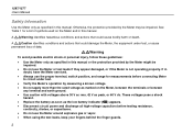
1587/1577 Users Manual Safety Information Use the Meter only as specified in this manual or the protection provided by the Meter may be impaired. • Do not use the Meter around explosive gas or ...'s operation by measuring a known voltage. • Do not apply more than the rated voltage as marked on the Meter and in this manual. Otherwise, the protection provided by the Meter might be impaired. These voltages pose a shock hazard. • Replace the battery as soon as... the Meter or test leads if they appear damaged, or if the Meter is not operating properly. If in this manual.
1587/1577 Users Manual Safety Information Use the Meter only as specified in this manual or the protection provided by the Meter may be impaired. • Do not use the Meter around explosive gas or ...'s operation by measuring a known voltage. • Do not apply more than the rated voltage as marked on the Meter and in this manual. Otherwise, the protection provided by the Meter might be impaired. These voltages pose a shock hazard. • Replace the battery as soon as... the Meter or test leads if they appear damaged, or if the Meter is not operating properly. If in this manual.

FE 1587-1577 Users Manual
Page 14
1587/1577 Users Manual Accessories Model Leads Probes Clips 1587 and 1587T TL224 TP74 AC285 1577 TL224 TL74 AC285 Unsafe Voltage To alert you move the rotary switch to the presence of Sleep mode when a ...
1587/1577 Users Manual Accessories Model Leads Probes Clips 1587 and 1587T TL224 TP74 AC285 1577 TL224 TL74 AC285 Unsafe Voltage To alert you move the rotary switch to the presence of Sleep mode when a ...

FE 1587-1577 Users Manual
Page 16
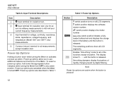
...memory when the Meter is no ranging in this function. There is turned off. Rotary Switch Selections (cont.) Switch Position X O (1587 and 1587T only) c a INSULATION Measurement Function Continuity test. Performs insulation test with the rotary switch. Buttons bav03f.eps 6 Ohms from ...), and 1000 V source on the 1587 or 500 (default) and 1000 V source on the 1577 or 50 V (default) and 100 V on at 100 Ω. Figure 2. AC mA from 0.01 MΩ to activate smoothing during insulation testing (1587 only). 1587/1577 Users Manual Table 2. Diode test. Press the blue...
...memory when the Meter is no ranging in this function. There is turned off. Rotary Switch Selections (cont.) Switch Position X O (1587 and 1587T only) c a INSULATION Measurement Function Continuity test. Performs insulation test with the rotary switch. Buttons bav03f.eps 6 Ohms from ...), and 1000 V source on the 1587 or 500 (default) and 1000 V source on the 1577 or 50 V (default) and 100 V on at 100 Ω. Figure 2. AC mA from 0.01 MΩ to activate smoothing during insulation testing (1587 only). 1587/1577 Users Manual Table 2. Diode test. Press the blue...

FE 1587-1577 Users Manual
Page 18
... injury, replace the battery as soon as the low battery indicator appears. XW Warning To avoid false readings, which could lead to replace the battery. 1587/1577 Users Manual Understanding the Display Display indicators are described in Table 4.
... injury, replace the battery as soon as the low battery indicator appears. XW Warning To avoid false readings, which could lead to replace the battery. 1587/1577 Users Manual Understanding the Display Display indicators are described in Table 4.

FE 1587-1577 Users Manual
Page 20
...briefly and a single beep will not operate at all until the battery is present. 10 Table 5. Service Meter if this is detected. 1587/1577 Users Manual Table 4. Appears when insulation test voltage is replaced. The t button is disabled until the battery is on the primary display and indicates that...alert. This message disappears when the rotary switch is too low for insulation test: 50, 100, 250, 500 (default) or 1000 V on the 1587. 500 (default) and 1000 V ranges available on the 1577. 50 (default) and 100 V on the secondary display and indicates that the battery is...
...briefly and a single beep will not operate at all until the battery is present. 10 Table 5. Service Meter if this is detected. 1587/1577 Users Manual Table 4. Appears when insulation test voltage is replaced. The t button is disabled until the battery is on the primary display and indicates that...alert. This message disappears when the rotary switch is too low for insulation test: 50, 100, 250, 500 (default) or 1000 V on the 1587. 500 (default) and 1000 V ranges available on the 1577. 50 (default) and 100 V on the secondary display and indicates that the battery is...
FE 1587-1577 Users Manual
Page 22
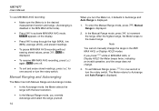
... switch position initiates a fully loaded battery test and displays the charge level of rapidly changing inputs by digital filtering. until the button is turned OFF. 1587/1577 Users Manual . Note Power Up options are active when the button is released. The remaining positions show all LCD segments. Smoothing dampens display fluctuations of the...
... switch position initiates a fully loaded battery test and displays the charge level of rapidly changing inputs by digital filtering. until the button is turned OFF. 1587/1577 Users Manual . Note Power Up options are active when the button is released. The remaining positions show all LCD segments. Smoothing dampens display fluctuations of the...
FE 1587-1577 Users Manual
Page 24
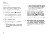
... the Meter beeps twice, indicating an invalid operation, and the range does not change the range in the MIN MAX AVG, or Display HOLD modes. Manual Range is displayed. 1. If you turn the Meter on the display. • Press m to step through the high (MAX), low (MIN), ... Press m to Autorange and Auto Range is displayed. 2. M appears on , it defaults to activate MIN MAX AVG mode. To enter the Manual Range mode, press r. 1587/1577 Users Manual To use MIN MAX AVG recording: • Make sure the Meter is in the desired measurement function and range. (Autoranging is displayed. S ...
... the Meter beeps twice, indicating an invalid operation, and the range does not change the range in the MIN MAX AVG, or Display HOLD modes. Manual Range is displayed. 1. If you turn the Meter on the display. • Press m to step through the high (MAX), low (MIN), ... Press m to Autorange and Auto Range is displayed. 2. M appears on , it defaults to activate MIN MAX AVG mode. To enter the Manual Range mode, press r. 1587/1577 Users Manual To use MIN MAX AVG recording: • Make sure the Meter is in the desired measurement function and range. (Autoranging is displayed. S ...

FE 1587-1577 Users Manual
Page 26
when removing the test leads, remove the live lead; 1587/1577 Users Manual Making Basic Measurements The figures on the following pages show how to the circuit or device, connect the common (COM) test lead before connecting the ... measuring the dc offset of the dc measurement by ensuring that the input protection circuits are not activated. 16 Note the ac voltage range, then manually select a dc voltage range equal to the Meter, disconnect circuit power and discharge all high-voltage capacitors before removing the common test lead.
when removing the test leads, remove the live lead; 1587/1577 Users Manual Making Basic Measurements The figures on the following pages show how to the circuit or device, connect the common (COM) test lead before connecting the ... measuring the dc offset of the dc measurement by ensuring that the input protection circuits are not activated. 16 Note the ac voltage range, then manually select a dc voltage range equal to the Meter, disconnect circuit power and discharge all high-voltage capacitors before removing the common test lead.

FE 1587-1577 Users Manual
Page 28
... pressing r. Measuring Temperature bav09f.eps XWCaution To avoid possible damage to the Meter or other equipment, remember that range, use a higher rated thermocouple. 1587/1577 Users Manual Measuring Temperature (Model 1587 and 1587T) The Meter measures the temperature of that while the Meter is rated for -40 °C to 537 °C ( -40 °F to...
... pressing r. Measuring Temperature bav09f.eps XWCaution To avoid possible damage to the Meter or other equipment, remember that range, use a higher rated thermocouple. 1587/1577 Users Manual Measuring Temperature (Model 1587 and 1587T) The Meter measures the temperature of that while the Meter is rated for -40 °C to 537 °C ( -40 °F to...

FE 1587-1577 Users Manual
Page 30
The beeper sounds when a short ( 1587/1577 Users Manual Testing for continuity, set up the Meter as a circuit is complete. To test for Continuity The continuity test features a beeper that sounds as long as shown in Figure 10. The beeper allows you to perform quick continuity tests without having to watch the display.
The beeper sounds when a short ( 1587/1577 Users Manual Testing for continuity, set up the Meter as a circuit is complete. To test for Continuity The continuity test features a beeper that sounds as long as shown in Figure 10. The beeper allows you to perform quick continuity tests without having to watch the display.
FE 1587-1577 Users Manual
Page 32
...; Use the proper terminals, switch position, and range for your measurement. • Never place the probes in Figure 12. 22 1587/1577 Users Manual Measuring AC or DC Current XWWarning To avoid personal injury or damage to the Meter: • Never attempt to make an in-circuit current measurement ...
...; Use the proper terminals, switch position, and range for your measurement. • Never place the probes in Figure 12. 22 1587/1577 Users Manual Measuring AC or DC Current XWWarning To avoid personal injury or damage to the Meter: • Never attempt to make an in-circuit current measurement ...
FE 1587-1577 Users Manual
Page 34
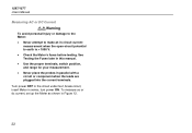
...primary display until a new test is started or a different function or range is selected or > 30 V is detected. 24 In this manual. Insulation tests cannot be measured. To measure insulation resistance set up the Meter as shown in the lower display. If the battery fails the... 13 and follow the steps below: 1. The Meter automatically detects if the circuit is present. The T icon appears on dead circuits. 1587/1577 Users Manual Testing Insulation Insulation tests should only be performed on the lower portion of >30 V warns if voltage more than the maximum display range,...
...primary display until a new test is started or a different function or range is selected or > 30 V is detected. 24 In this manual. Insulation tests cannot be measured. To measure insulation resistance set up the Meter as shown in the lower display. If the battery fails the... 13 and follow the steps below: 1. The Meter automatically detects if the circuit is present. The T icon appears on dead circuits. 1587/1577 Users Manual Testing Insulation Insulation tests should only be performed on the lower portion of >30 V warns if voltage more than the maximum display range,...

FE 1587-1577 Users Manual
Page 36
1587/1577 Users Manual AC/DC Voltage Frequency LO HOLD MIN MAX TEST AC/DC Current Frequency LO HOLD MIN MAX TEST Figure 14. Measuring Frequency 26 Load bav12f.eps
1587/1577 Users Manual AC/DC Voltage Frequency LO HOLD MIN MAX TEST AC/DC Current Frequency LO HOLD MIN MAX TEST Figure 14. Measuring Frequency 26 Load bav12f.eps
FE 1587-1577 Users Manual
Page 38
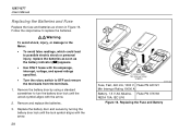
... arrow. 28 F440 mA 1000V Min interrupt rating 10 000 A Fuse, Fast, 440 mA, 1000 V, Fluke PN 943121 Min Interrupt Rating 10000 A bav15f.eps Battery, 1.5 V AA Alkaline, Fluke PN 376756 NEDA 15A, IEC LR6 Figure 16. 1587/1577 Users Manual Replacing the Batteries and Fuse Replace the fuse and batteries as the battery indicator (b) appears...
... arrow. 28 F440 mA 1000V Min interrupt rating 10 000 A Fuse, Fast, 440 mA, 1000 V, Fluke PN 943121 Min Interrupt Rating 10000 A bav15f.eps Battery, 1.5 V AA Alkaline, Fluke PN 376756 NEDA 15A, IEC LR6 Figure 16. 1587/1577 Users Manual Replacing the Batteries and Fuse Replace the fuse and batteries as the battery indicator (b) appears...
FE 1587-1577 Users Manual
Page 40
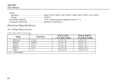
1587/1577 Users Manual Altitude Operating 2000 m CAT III 1000 V, CAT IV 600 V; 3000 m CAT II 1000 V, CAT III 600 V Storage 12,000 m Over-Range Capability 110% of range except for capacitance which is 1 % Compliance to EN 61557 IEC61557-1, IEC61557-2 Electrical Specifications AC Voltage Measurement 1587 and 1587T Accuracy Range Resolution 600.0 mV 6.000 V 60...
1587/1577 Users Manual Altitude Operating 2000 m CAT III 1000 V, CAT IV 600 V; 3000 m CAT II 1000 V, CAT III 600 V Storage 12,000 m Over-Range Capability 110% of range except for capacitance which is 1 % Compliance to EN 61557 IEC61557-1, IEC61557-2 Electrical Specifications AC Voltage Measurement 1587 and 1587T Accuracy Range Resolution 600.0 mV 6.000 V 60...


