
FE 1587-1577 Users Manual
Page 2
..., or damaged by use and service. Fluke assumes no authority to extend a greater or different warranty on the date of a defective product which , in another country. If Fluke determines that software will operate substantially in accordance with its functional specifications for 90 days and that service center, with a description of repair/replacement parts when product purchased in transit. Fluke Corporation P.O. LIMITED WARRANTY...
..., or damaged by use and service. Fluke assumes no authority to extend a greater or different warranty on the date of a defective product which , in another country. If Fluke determines that software will operate substantially in accordance with its functional specifications for 90 days and that service center, with a description of repair/replacement parts when product purchased in transit. Fluke Corporation P.O. LIMITED WARRANTY...

FE 1587-1577 Users Manual
Page 3
Table of Contents Title Page Introduction ...1 Contacting Fluke ...1 Safety Information ...2 Accessories ...4 Unsafe Voltage...4 Test Lead Alert ...4 Battery Saver (Sleep Mode 4 Rotary Switch Positions 5 Buttons ...6 Understanding the Display 8 Input Terminals...11 Power-Up Options ...12 AutoHold Mode...13 MIN MAX AVG Recording Mode 13 Manual Ranging and Autoranging 14 Understanding AC Zero Input Behavior of True RMS Meters 15 Low-Pass Filter (Model 1587 and 1587T 15 i
Table of Contents Title Page Introduction ...1 Contacting Fluke ...1 Safety Information ...2 Accessories ...4 Unsafe Voltage...4 Test Lead Alert ...4 Battery Saver (Sleep Mode 4 Rotary Switch Positions 5 Buttons ...6 Understanding the Display 8 Input Terminals...11 Power-Up Options ...12 AutoHold Mode...13 MIN MAX AVG Recording Mode 13 Manual Ranging and Autoranging 14 Understanding AC Zero Input Behavior of True RMS Meters 15 Low-Pass Filter (Model 1587 and 1587T 15 i

FE 1587-1577 Users Manual
Page 4
... 21 Measuring AC or DC Current 22 Testing Insulation ...24 Measuring Frequency (Model 1587 and 1587T 25 Cleaning...27 Testing the Batteries ...27 Testing the Fuse ...27 Replacing the Batteries and Fuse 28 Specifications...29 General Specifications 29 Electrical Specifications 30 AC Voltage Measurement 30 1587 and 1587T Accuracy 30 1587 and 1587T Low-Pass Filter Voltage 31 1577 Accuracy...31 DC Voltage...
... 21 Measuring AC or DC Current 22 Testing Insulation ...24 Measuring Frequency (Model 1587 and 1587T 25 Cleaning...27 Testing the Batteries ...27 Testing the Fuse ...27 Replacing the Batteries and Fuse 28 Specifications...29 General Specifications 29 Electrical Specifications 30 AC Voltage Measurement 30 1587 and 1587T Accuracy 30 1587 and 1587T Low-Pass Filter Voltage 31 1577 Accuracy...31 DC Voltage...
FE 1587-1577 Users Manual
Page 11
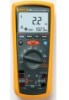
...the primary supply level (overhead or underground utility service). CAT IV meters are designed to protect against transients in the world Visit Fluke's web site at: www.fluke.com Register your Meter at ...installations at : register.fluke.com 1 CAT III meters are battery-powered, true-RMS insulation multimeters (hereafter "the Meter") with a 6000-count and a 3 ¾ digit display. 1587/1577 Insulation Multimeters Introduction The Fluke Models 1587,1587T, and 1577 are designed to IV) based on the magnitude of Model 1587. Although this manual describes the operation of all models...
...the primary supply level (overhead or underground utility service). CAT IV meters are designed to protect against transients in the world Visit Fluke's web site at: www.fluke.com Register your Meter at ...installations at : register.fluke.com 1 CAT III meters are battery-powered, true-RMS insulation multimeters (hereafter "the Meter") with a 6000-count and a 3 ¾ digit display. 1587/1577 Insulation Multimeters Introduction The Fluke Models 1587,1587T, and 1577 are designed to IV) based on the magnitude of Model 1587. Although this manual describes the operation of all models...
FE 1587-1577 Users Manual
Page 12
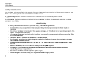
... specified in doubt, have the Meter serviced. • Always use the proper terminal, switch position, and range for a list of data. See Table 1 for measurements before testing resistance, continuity, diodes, or capacitance. • Do not use the Meter or test leads if they appear damaged, or if the Meter is not operating properly. If in this manual or the protection provided by...
... specified in doubt, have the Meter serviced. • Always use the proper terminal, switch position, and range for a list of data. See Table 1 for measurements before testing resistance, continuity, diodes, or capacitance. • Do not use the Meter or test leads if they appear damaged, or if the Meter is not operating properly. If in this manual or the protection provided by...
FE 1587-1577 Users Manual
Page 13
... (Alternating Current) DC (Direct Current) WARNING: risk of electric shock. see manual 3 Do not use . Insulation Multimeters Safety Information • Remove test leads from the Meter before use if the readings are high or noisy. Battery (Low battery when shown on display.) J I T W Earth Ground Fuse Double Insulated Important information; B F X b Table 1. Never operate the Meter with the cover removed or the battery door open. •...
... (Alternating Current) DC (Direct Current) WARNING: risk of electric shock. see manual 3 Do not use . Insulation Multimeters Safety Information • Remove test leads from the Meter before use if the readings are high or noisy. Battery (Low battery when shown on display.) J I T W Earth Ground Fuse Double Insulated Important information; B F X b Table 1. Never operate the Meter with the cover removed or the battery door open. •...

FE 1587-1577 Users Manual
Page 14
... in the correct terminals, LEAd is displayed. XW Warning To avoid a blown fuse, damage to the Meter, or serious personal injury, never attempt to the presence of Sleep mode when a key is pressed or when the rotary switched is no function change or button press for 20 minutes. 1587/1577 Users Manual Accessories Model Leads Probes Clips 1587 and 1587T TL224 TP74 AC285 1577...
... in the correct terminals, LEAd is displayed. XW Warning To avoid a blown fuse, damage to the Meter, or serious personal injury, never attempt to the presence of Sleep mode when a key is pressed or when the rotary switched is no function change or button press for 20 minutes. 1587/1577 Users Manual Accessories Model Leads Probes Clips 1587 and 1587T TL224 TP74 AC285 1577...

FE 1587-1577 Users Manual
Page 16
... turned off. Buttons Use the buttons to 400 mA (600 mA overload for 2 minutes maximum). Beeper turns on the 1587T. DC mA from 0.01 MΩ to 2 GΩ. 1587/1577 Users Manual Table 2. Displays 0L above 6.600 V. Press the blue button to 400 mA (600 mA overload for 2 minutes maximum). Figure 2. The last selected high voltage setting is retained in memory when the Meter...
... turned off. Buttons Use the buttons to 400 mA (600 mA overload for 2 minutes maximum). Beeper turns on the 1587T. DC mA from 0.01 MΩ to 2 GΩ. 1587/1577 Users Manual Table 2. Displays 0L above 6.600 V. Press the blue button to 400 mA (600 mA overload for 2 minutes maximum). Figure 2. The last selected high voltage setting is retained in memory when the Meter...
FE 1587-1577 Users Manual
Page 17
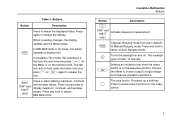
... a test lock the next time you press t on the Meter or on the rotary switch. 7 G Press to cancel MIN MAX AVG. When a reading changes, the display updates and the Meter beeps. In Insulation Test mode, this button operates a display hold to access blue functions on the remote probe. The blue button. Buttons Button Description Press to release the display. Press again to freeze the displayed value. Insulation Multimeters Buttons Button Description f (1587 and...
... a test lock the next time you press t on the Meter or on the rotary switch. 7 G Press to cancel MIN MAX AVG. When a reading changes, the display updates and the Meter beeps. In Insulation Test mode, this button operates a display hold to access blue functions on the remote probe. The blue button. Buttons Button Description Press to release the display. Press again to freeze the displayed value. Insulation Multimeters Buttons Button Description f (1587 and...

FE 1587-1577 Users Manual
Page 20
... Meter will sound when you move the switch in use Source voltage rating for reliable operation. Appears when insulation test voltage is detected. Service Meter if this is too low to any other function. The message appears briefly and a single beep will not operate at all until the battery is turned to perform an insulation test. 1587/1577 Users Manual Table 4. Model detect error. Appears...
... Meter will sound when you move the switch in use Source voltage rating for reliable operation. Appears when insulation test voltage is detected. Service Meter if this is too low to any other function. The message appears briefly and a single beep will not operate at all until the battery is turned to perform an insulation test. 1587/1577 Users Manual Table 4. Model detect error. Appears...
FE 1587-1577 Users Manual
Page 22
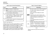
... battery until the button is pressed. C Input terminal for ac and dc milliamp measurements to use additional features and functions of rapidly changing inputs by digital filtering. Smoothing dampens display fluctuations of the Meter. Power-up options are described in Table 7. 12 Table 7. Power-up options allow you to 400 mA and current frequency measurements. C switch position displays the software version number. Power-Up Options Button S r Description B switch position turns...
... battery until the button is pressed. C Input terminal for ac and dc milliamp measurements to use additional features and functions of rapidly changing inputs by digital filtering. Smoothing dampens display fluctuations of the Meter. Power-up options are described in Table 7. 12 Table 7. Power-up options allow you to 400 mA and current frequency measurements. C switch position displays the software version number. Power-Up Options Button S r Description B switch position turns...
FE 1587-1577 Users Manual
Page 23
... used to determine if a circuit is live. Starts the Calibration mode. When the inputs go below the recorded minimum value or above the recorded maximum value, the Meter beeps and records the new value. The Meter tracks the minimum, maximum, and average values for each display which are operating the equipment under test and cannot watch the Meter. Power-Up Options (cont.) Button Description G (Blue) H t Disables automatic power...
... used to determine if a circuit is live. Starts the Calibration mode. When the inputs go below the recorded minimum value or above the recorded maximum value, the Meter beeps and records the new value. The Meter tracks the minimum, maximum, and average values for each display which are operating the equipment under test and cannot watch the Meter. Power-Up Options (cont.) Button Description G (Blue) H t Disables automatic power...
FE 1587-1577 Users Manual
Page 24
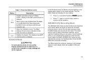
... turn the rotary switch. In the Manual Range mode, press r to Autorange and Auto Range is displayed. 1587/1577 Users Manual To use MIN MAX AVG recording: • Make sure the Meter is in the desired measurement function and range. (Autoranging is disabled in the MIN MAX AVG, or Display HOLD modes. After the highest range, the Meter wraps to Autorange and Auto Range is displayed. 1. Note You cannot manually change . 3. M appears on , it defaults...
... turn the rotary switch. In the Manual Range mode, press r to Autorange and Auto Range is displayed. 1587/1577 Users Manual To use MIN MAX AVG recording: • Make sure the Meter is in the desired measurement function and range. (Autoranging is disabled in the MIN MAX AVG, or Display HOLD modes. After the highest range, the Meter wraps to Autorange and Auto Range is displayed. 1. Note You cannot manually change . 3. M appears on , it defaults...
FE 1587-1577 Users Manual
Page 25
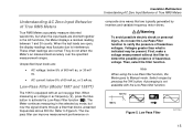
... filter can improve measurement performance on Insulation Multimeters Understanding AC Zero Input Behavior of True RMS Meters composite sine waves that blocks unwanted frequencies above 800 Hz. Select ranges by inverters and variable frequency motor drives. When measuring ac voltage or ac frequency (B), press the blue button to Manual mode. XWWarning To avoid possible electric shock or personal injury, do...
... filter can improve measurement performance on Insulation Multimeters Understanding AC Zero Input Behavior of True RMS Meters composite sine waves that blocks unwanted frequencies above 800 Hz. Select ranges by inverters and variable frequency motor drives. When measuring ac voltage or ac frequency (B), press the blue button to Manual mode. XWWarning To avoid possible electric shock or personal injury, do...

FE 1587-1577 Users Manual
Page 28
... Temperature bav09f.eps XWWarning To avoid risk of shock do not connect thermocouple to 998.0 °F), the included K-type thermocouple is rated for 260 °C (500 °F). 1587/1577 Users Manual Measuring Temperature (Model 1587 and 1587T) The Meter measures the temperature of that while the Meter is rated for -40 °C to 537 °C ( ...;F 80BK1 Type K Thermocouple Probe Vent or Pipe Figure 7. For temperatures out of a type-K thermocouple (included). XWCaution To avoid possible damage to the Meter or other equipment, remember that range, use a higher rated thermocouple.
... Temperature bav09f.eps XWWarning To avoid risk of shock do not connect thermocouple to 998.0 °F), the included K-type thermocouple is rated for 260 °C (500 °F). 1587/1577 Users Manual Measuring Temperature (Model 1587 and 1587T) The Meter measures the temperature of that while the Meter is rated for -40 °C to 537 °C ( ...;F 80BK1 Type K Thermocouple Probe Vent or Pipe Figure 7. For temperatures out of a type-K thermocouple (included). XWCaution To avoid possible damage to the Meter or other equipment, remember that range, use a higher rated thermocouple.
FE 1587-1577 Users Manual
Page 34
... be performed on the primary display until a new test is started or a different function or range is selected or > 30 V is energized. • The primary display shows - - - - The circuit under test. 1587/1577 Users Manual Testing Insulation Insulation tests should only be performed until the batteries are replaced. 3. See Testing the Fuse later in the lower display. Turn the knob to be measured...
... be performed on the primary display until a new test is started or a different function or range is selected or > 30 V is energized. • The primary display shows - - - - The circuit under test. 1587/1577 Users Manual Testing Insulation Insulation tests should only be performed until the batteries are replaced. 3. See Testing the Fuse later in the lower display. Turn the knob to be measured...

FE 1587-1577 Users Manual
Page 35
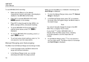
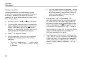
... the number of times the signal crosses a threshold level each second. Turn the rotary switch to select dc if needed. 4. To measure frequency, set up the Meter as shown in Figure 14 and follow the steps below. 1. Press the f button. 5. In the c position press the blue button to the B, C, or c position. 3. Press the blue button, the f button, or change the rotary switch position to the signal source. 2. Connect the Meter...
... the number of times the signal crosses a threshold level each second. Turn the rotary switch to select dc if needed. 4. To measure frequency, set up the Meter as shown in Figure 14 and follow the steps below. 1. Press the f button. 5. In the c position press the blue button to the B, C, or c position. 3. Press the blue button, the f button, or change the rotary switch position to the signal source. 2. Connect the Meter...
FE 1587-1577 Users Manual
Page 37
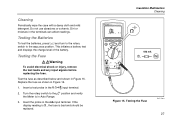
... verify the Meter is bad and should be replaced. Turn the rotary switch to the INSULATION position. Test the fuse as shown in the J input terminal. 2. Insert the probe in Figure 15. Dirt or moisture in Auto Range. 3. Testing the Fuse XWWarning To avoid electrical shock or injury, remove the test leads and any input signals before replacing the fuse. Do not use abrasives...
... verify the Meter is bad and should be replaced. Turn the rotary switch to the INSULATION position. Test the fuse as shown in the J input terminal. 2. Insert the probe in Figure 15. Dirt or moisture in Auto Range. 3. Testing the Fuse XWWarning To avoid electrical shock or injury, remove the test leads and any input signals before replacing the fuse. Do not use abrasives...
FE 1587-1577 Users Manual
Page 38
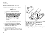
... turn the battery door lock until the lock symbol aligns with the arrow. 28 F440 mA 1000V Min interrupt rating 10 000 A Fuse, Fast, 440 mA, 1000 V, Fluke PN 943121 Min Interrupt Rating 10000 A bav15f.eps Battery, 1.5 V AA Alkaline, Fluke PN 376756 NEDA 15A, IEC LR6 Figure 16. 1587/1577 Users Manual Replacing the Batteries and Fuse Replace the fuse and batteries as the battery indicator (b) appears. • Use...
... turn the battery door lock until the lock symbol aligns with the arrow. 28 F440 mA 1000V Min interrupt rating 10 000 A Fuse, Fast, 440 mA, 1000 V, Fluke PN 943121 Min Interrupt Rating 10000 A bav15f.eps Battery, 1.5 V AA Alkaline, Fluke PN 376756 NEDA 15A, IEC LR6 Figure 16. 1587/1577 Users Manual Replacing the Batteries and Fuse Replace the fuse and batteries as the battery indicator (b) appears. • Use...
FE 1587-1577 Users Manual
Page 46
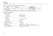
Insulation Specifications Measurement Range Model 1587 0.01 MΩ to 2 GΩ Model 1577 0.1 MΩ to 600 MΩ Model 1587T 0.01 MΩ to 100 MΩ Test Voltages Model 1587 50, 100, 250, 500, 1000 V Model 1577 500, 1000 V Model 1587T 50, 100 V Test Voltage Accuracy 20 %, - 0 % Short-Circuit Test Current 1 mA nominal Auto Discharge Discharge time 30 V prior to initialization of the instrument. 1587/1577 Users Manual Temperature...
Insulation Specifications Measurement Range Model 1587 0.01 MΩ to 2 GΩ Model 1577 0.1 MΩ to 600 MΩ Model 1587T 0.01 MΩ to 100 MΩ Test Voltages Model 1587 50, 100, 250, 500, 1000 V Model 1577 500, 1000 V Model 1587T 50, 100 V Test Voltage Accuracy 20 %, - 0 % Short-Circuit Test Current 1 mA nominal Auto Discharge Discharge time 30 V prior to initialization of the instrument. 1587/1577 Users Manual Temperature...


