
Service Manual
Page 2
...on non-defective media. Fluke reserves the right to invoice Buyer for importation costs of repair/replacement parts when product purchased in one year for its functional specifications for 90 days...Fluke authorized reseller, and does not apply to fuses, disposable batteries or to the original buyer or end-user customer of Fluke. Fluke's warranty obligation is purchased through a Fluke authorized sales outlet or Buyer has paid the applicable international price. To obtain warranty service, contact your nearest Fluke authorized service center or send the product, with its accessories...
...on non-defective media. Fluke reserves the right to invoice Buyer for importation costs of repair/replacement parts when product purchased in one year for its functional specifications for 90 days...Fluke authorized reseller, and does not apply to fuses, disposable batteries or to the original buyer or end-user customer of Fluke. Fluke's warranty obligation is purchased through a Fluke authorized sales outlet or Buyer has paid the applicable international price. To obtain warranty service, contact your nearest Fluke authorized service center or send the product, with its accessories...

Service Manual
Page 13
... maintenance procedures to prevent damage to or destruction of Replaceable Parts. Warning Calls attention to a potential danger that both operating and service personnel follow generally accepted safety procedures in addition to install and use of detailed specifications. This Service Manual provides the information necessary to prevent personal injury. 1-3 Chapter 5. Chapter 6. List of the equipment or other property. To avoid electrical shock...
... maintenance procedures to prevent damage to or destruction of Replaceable Parts. Warning Calls attention to a potential danger that both operating and service personnel follow generally accepted safety procedures in addition to install and use of detailed specifications. This Service Manual provides the information necessary to prevent personal injury. 1-3 Chapter 5. Chapter 6. List of the equipment or other property. To avoid electrical shock...

Service Manual
Page 19
...;C. Auto Set (Connect-and-ViewTM) Continuous fully automatic adjustment of waveforms over time. Add 0.1x (specific accuracy) for each °C below 18 °C or above 28 °C. 2 Characteristics 2.3 Dual Input Meter Source Sensitivity A and B (Fluke 123) @ DC to 5 MHz @ 25 MHz @ 40 MHz Sensitivity A and B (Fluke 124, 125) @ DC to 5 MHz @ 40 MHz @ 60 MHz Voltage level error Slope Video on the screen. 2.3.1 Input...
...;C. Auto Set (Connect-and-ViewTM) Continuous fully automatic adjustment of waveforms over time. Add 0.1x (specific accuracy) for each °C below 18 °C or above 28 °C. 2 Characteristics 2.3 Dual Input Meter Source Sensitivity A and B (Fluke 123) @ DC to 5 MHz @ 25 MHz @ 40 MHz Sensitivity A and B (Fluke 124, 125) @ DC to 5 MHz @ 40 MHz @ 60 MHz Voltage level error Slope Video on the screen. 2.3.1 Input...
Service Manual
Page 26
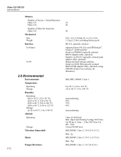
... isolated RS232/USB adapter/cable, optional), using SW90W (FlukeView software for Windows). 2.8 Environmental Environmental Temperature Operating Storage Humidity Operating: @0 to...Serial via PAC91 (optically isolated print adapter cable, optional). Dump and load settings and data. Fluke 123/124/125 Service Manual Memory Number of Screen + Setup Memories Fluke 123 Fluke 124 Number of Data Set memories Fluke 125 Mechanical Size Weight Interface To Printer To PC 10 20 20 232 x 115 x 50 mm (9.1 x 4.5 x 2 in) 1.2 kg (2.5 lbs), including battery pack. RS-232, optically isolated supports...
... isolated RS232/USB adapter/cable, optional), using SW90W (FlukeView software for Windows). 2.8 Environmental Environmental Temperature Operating Storage Humidity Operating: @0 to...Serial via PAC91 (optically isolated print adapter cable, optional). Dump and load settings and data. Fluke 123/124/125 Service Manual Memory Number of Screen + Setup Memories Fluke 123 Fluke 124 Number of Data Set memories Fluke 125 Mechanical Size Weight Interface To Printer To PC 10 20 20 232 x 115 x 50 mm (9.1 x 4.5 x 2 in) 1.2 kg (2.5 lbs), including battery pack. RS-232, optically isolated supports...

Service Manual
Page 33
... have a Fluke 5500A with the Fluke 123. • Dual Banana Plug to Female BNC Adapter (1x), Fluke PM9081/001. • Dual Banana Jack to Male BNC Adapter (1x), Fluke PM9082/001. • TV Signal Generator, Philips PM5418. • 75Ω Coax cable (1x), Fluke PM9075. • 75Ω Feed through termination, and a Fluke PM9082/001 Adapter. If a 5500A is in a proper operating condition. To...
... have a Fluke 5500A with the Fluke 123. • Dual Banana Plug to Female BNC Adapter (1x), Fluke PM9081/001. • Dual Banana Jack to Male BNC Adapter (1x), Fluke PM9082/001. • TV Signal Generator, Philips PM5418. • 75Ω Coax cable (1x), Fluke PM9075. • 75Ω Feed through termination, and a Fluke PM9082/001 Adapter. If a 5500A is in a proper operating condition. To...

Service Manual
Page 34
... on , and start at 5. 8. Press (PREV) three times. Fluke 124/125: press , then press . The test tool shows the calibration menu in requirements for the display function and measure functions follow. Press (CAL) . For each test point , wait for the 5500A to the test tool via a 50Ω Coax Cable and terminated with the PM8907 power adapter. Differences in...
... on , and start at 5. 8. Press (PREV) three times. Fluke 124/125: press , then press . The test tool shows the calibration menu in requirements for the display function and measure functions follow. Press (CAL) . For each test point , wait for the 5500A to the test tool via a 50Ω Coax Cable and terminated with the PM8907 power adapter. Differences in...

Service Manual
Page 37
... circuit the Input A and the Input B shielded banana sockets of Input B between AUTO and MANUAL ranging). • Fluke 123/124: press / to open the SCOPE INPUTS menu. • Fluke 123/124: press to open the SCOPE OPTIONS menu, and choose : SCOPE MODE: NORMAL | WAVEFORM MODE: SMOOTH • Fluke 125: press to open MENU. • Fluke 125: press to open the TRIGGER menu, and choose : UPDATE: FREE RUN • Fluke 125...
... circuit the Input A and the Input B shielded banana sockets of Input B between AUTO and MANUAL ranging). • Fluke 123/124: press / to open the SCOPE INPUTS menu. • Fluke 123/124: press to open the SCOPE OPTIONS menu, and choose : SCOPE MODE: NORMAL | WAVEFORM MODE: SMOOTH • Fluke 125: press to open MENU. • Fluke 125: press to open the TRIGGER menu, and choose : UPDATE: FREE RUN • Fluke 125...

Service Manual
Page 38
... press anymore! • Using change the sensitivity to select manual sensitivity ranging, and lock the Input A sensitivity on the display. 5. Set the 5500A to 1.5 divisions on the test tool display. 8. If it is not, press to enable the up /down arrow keys for Trigger Level adjustment; adjust the trigger level using and verify that the signal will be triggered now. 3-8 Connect the test tool to...
... press anymore! • Using change the sensitivity to select manual sensitivity ranging, and lock the Input A sensitivity on the display. 5. Set the 5500A to 1.5 divisions on the test tool display. 8. If it is not, press to enable the up /down arrow keys for Trigger Level adjustment; adjust the trigger level using and verify that the signal will be triggered now. 3-8 Connect the test tool to...

Service Manual
Page 39
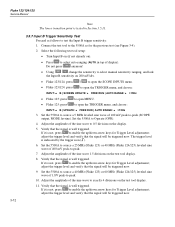
...; Using change the sensitivity to select auto ranging (AUTO in Section 3.5.11. 3.5.4 Input A Frequency Measurement Accuracy Test Proceed as follows to test the Input A frequency response upper transition point: 1. Select the following test tool setup: • Press to select manual sensitivity ranging, and lock the Input A sensitivity on A: Hz 3. Select the following test tool setup: • Press to select auto ranging (AUTO in Table 3-1. 3-9 Adjust the amplitude of display). •...
...; Using change the sensitivity to select auto ranging (AUTO in Section 3.5.11. 3.5.4 Input A Frequency Measurement Accuracy Test Proceed as follows to test the Input A frequency response upper transition point: 1. Select the following test tool setup: • Press to select manual sensitivity ranging, and lock the Input A sensitivity on A: Hz 3. Select the following test tool setup: • Press to select auto ranging (AUTO in Table 3-1. 3-9 Adjust the amplitude of display). •...

Service Manual
Page 41
... to open the TRIGGER menu, and choose : INPUT: B | UPDATE: FREE RUN | AUTO RANGE: >15Hz 3. When you are finished, set the 5500A to -peak (SCOPE output, MODE levsine). Continue through the test points. 7. to open the TRIGGER menu, and choose: INPUT: B | SCREEN UPDATE: FREE RUN | AUTO RANGE: >15Hz • Fluke 125: press to open MENU. • Fluke 125: press to test the Input B frequency response upper transition point: 1. Connect the test tool to...
... to open the TRIGGER menu, and choose : INPUT: B | UPDATE: FREE RUN | AUTO RANGE: >15Hz 3. When you are finished, set the 5500A to -peak (SCOPE output, MODE levsine). Continue through the test points. 7. to open the TRIGGER menu, and choose: INPUT: B | SCREEN UPDATE: FREE RUN | AUTO RANGE: >15Hz • Fluke 125: press to open MENU. • Fluke 125: press to test the Input B frequency response upper transition point: 1. Connect the test tool to...
Service Manual
Page 42
... to open MENU. • Fluke 125: press to select manual sensitivity ranging, and lock the Input B sensitivity on the display. 5. Verify that the signal will be triggered now. 9. Do not press anymore! • Using change the sensitivity to open the TRIGGER menu, and choose : INPUT: B | UPDATE: FREE RUN | AUTO RANGE: >15Hz 3. The trigger level is not, press to exactly 4 divisions on the test tool display. 8. Adjust the amplitude...
... to open MENU. • Fluke 125: press to select manual sensitivity ranging, and lock the Input B sensitivity on the display. 5. Verify that the signal will be triggered now. 9. Do not press anymore! • Using change the sensitivity to open the TRIGGER menu, and choose : INPUT: B | UPDATE: FREE RUN | AUTO RANGE: >15Hz 3. The trigger level is not, press to exactly 4 divisions on the test tool display. 8. Adjust the amplitude...
Service Manual
Page 46
... column of display). • Press to open the INPUT A MEASUREMENTS menu, and choose: MEASURE on A: Vdc • Press to open the INPUT B MEASUREMENTS menu, and choose: INPUT B: ON | MEASURE on B: Vdc • Using change the time base to select manual time base ranging, and lock the time base on the calibration source and connecting cables during the following test tool setup: • Press select auto ranging (AUTO in standby mode before making...
... column of display). • Press to open the INPUT A MEASUREMENTS menu, and choose: MEASURE on A: Vdc • Press to open the INPUT B MEASUREMENTS menu, and choose: INPUT B: ON | MEASURE on B: Vdc • Using change the time base to select manual time base ranging, and lock the time base on the calibration source and connecting cables during the following test tool setup: • Press select auto ranging (AUTO in standby mode before making...
Service Manual
Page 48
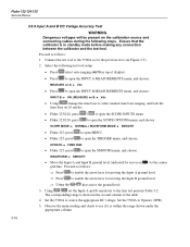
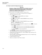
... arrow keys for the previous test (see if it is within the range shown under the appropriate column. 6. Set the 5500A to see Figure 3-5). 2. Fluke 123/124/125 Service Manual 3.5.10 Input A and B AC Voltage Accuracy Test Warning Dangerous voltages will be present on the calibration source and connecting cables during the following test tool setup: • Press to select auto ranging (AUTO in...
... arrow keys for the previous test (see if it is within the range shown under the appropriate column. 6. Set the 5500A to see Figure 3-5). 2. Fluke 123/124/125 Service Manual 3.5.10 Input A and B AC Voltage Accuracy Test Warning Dangerous voltages will be present on the calibration source and connecting cables during the following test tool setup: • Press to select auto ranging (AUTO in...

Service Manual
Page 49
... menu, and choose: • Fluke 125: press to open the B INPUT menu, and choose: INPUT B: AC | NORMAL • Fluke 125: press to open MENU. • Fluke 125: press to open the TRIGGER menu, and choose: UPDATE: FREE RUN | AUTO RANGE: > 1Hz 3. Set the 5500A to test the Input A and B AC coupled input lower transition point: 1. Select the following test tool setup: • Use the setup of the previous step (AUTO time...
... menu, and choose: • Fluke 125: press to open the B INPUT menu, and choose: INPUT B: AC | NORMAL • Fluke 125: press to open MENU. • Fluke 125: press to open the TRIGGER menu, and choose: UPDATE: FREE RUN | AUTO RANGE: > 1Hz 3. Set the 5500A to test the Input A and B AC coupled input lower transition point: 1. Select the following test tool setup: • Use the setup of the previous step (AUTO time...
Service Manual
Page 50
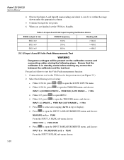
... calibration source and connecting cables during the following test tool setup: • Fluke 123/124: press • Fluke 123/124: press / to open the TRIGGER menu, and choose : INPUT: A | UPDATE: FREE RUN | AUTO RANGE: > 15Hz • Press to open the INPUT B MEASUREMENTS menu, and choose: INPUT B: ON | MEASURE on A: PEAK From the INPUT A PEAK sub-menu choose: PEAK TYPE : PEAK-PEAK • Press to select auto ranging (AUTO in standby mode...
... calibration source and connecting cables during the following test tool setup: • Fluke 123/124: press • Fluke 123/124: press / to open the TRIGGER menu, and choose : INPUT: A | UPDATE: FREE RUN | AUTO RANGE: > 15Hz • Press to open the INPUT B MEASUREMENTS menu, and choose: INPUT B: ON | MEASURE on A: PEAK From the INPUT A PEAK sub-menu choose: PEAK TYPE : PEAK-PEAK • Press to select auto ranging (AUTO in standby mode...

Service Manual
Page 67
... last time this step are shown using the new calibration data. 4-5 or b. Functions of the keys F1-F4 are shown for Input A and Input B. This calibration step is only required if the display cannot made dark or light enough, or if the display after a test tool reset is not started . It does not necessarily mean that the unit meets the specifications related to Section 4.4 Contrast Calibration Adjustment. The calibration data...
... last time this step are shown using the new calibration data. 4-5 or b. Functions of the keys F1-F4 are shown for Input A and Input B. This calibration step is only required if the display cannot made dark or light enough, or if the display after a test tool reset is not started . It does not necessarily mean that the unit meets the specifications related to Section 4.4 Contrast Calibration Adjustment. The calibration data...

Service Manual
Page 78
..., and calibrate the test tool, starting at power on the test tool display: WARNING.Calibration data NOT valid. Fluke 123/124/125 Service Manual Possible error messages. Calibration data will show the message The test tool needs calibration. Please contact your service center at Section 4.5. • To exit and save the calibration data: ⇒ Press NO The test tool returns to the maintenance mode. Then supply the correct adapter input voltage...
..., and calibrate the test tool, starting at power on the test tool display: WARNING.Calibration data NOT valid. Fluke 123/124/125 Service Manual Possible error messages. Calibration data will show the message The test tool needs calibration. Please contact your service center at Section 4.5. • To exit and save the calibration data: ⇒ Press NO The test tool returns to the maintenance mode. Then supply the correct adapter input voltage...

Service Manual
Page 86
... new top case, if you must follow special precautions when reassembling the test tool. If you re-install the unit's original display assembly. Install the keypad foil. Refer also to install the power connector insulator (item 3) and the LED holder (item 6). 3. Keep the lens free of the lens with a yellow tube on the PCA), and shielding plate, as spare part...
... new top case, if you must follow special precautions when reassembling the test tool. If you re-install the unit's original display assembly. Install the keypad foil. Refer also to install the power connector insulator (item 3) and the LED holder (item 6). 3. Keep the lens free of the lens with a yellow tube on the PCA), and shielding plate, as spare part...

Service Manual
Page 95
... must be downloaded from Fluke's website www.fluke.com 6-7 For other countries, a line plug adapter complying with UL listed line plug adapter for use in North America. PM8907/801 PM8907/803 PM8907/804 PM8907/806 PM8907/807 PM8907/808 Set of two Shielded Test Leads (Red and Gray), designed for North America. 6.6 Service Tools Power adapter cable to check supply current 5322 320 11707 6.7 Accessory Replacement Parts 6 List of two...
... must be downloaded from Fluke's website www.fluke.com 6-7 For other countries, a line plug adapter complying with UL listed line plug adapter for use in North America. PM8907/801 PM8907/803 PM8907/804 PM8907/806 PM8907/807 PM8907/808 Set of two Shielded Test Leads (Red and Gray), designed for North America. 6.6 Service Tools Power adapter cable to check supply current 5322 320 11707 6.7 Accessory Replacement Parts 6 List of two...
Service Manual
Page 96
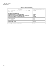
Optional Accessories Description Model Number/Ordering Code Software & Cable Carrying Case Kit (Supplied with Fluke 123/S, 124/S, 125/S FlukeView®ScopeMeter® Softwarefor Windows® Hard Carrying Case Compact Soft Case Isolated Trigger Probe Print Adapter Cable for Parallel Printers SCC 120 OC4USB C120 SW90W C120 C125 ITP120 PAC91 6-8 Fluke 123/124/125 Service Manual Table 6-4. Supplied with Fluke 123/S, 124/S, 125/S) Set contains the following parts: Optically Isolated RS-232/USBAdapter/Cable Hard Carrying Case.
Optional Accessories Description Model Number/Ordering Code Software & Cable Carrying Case Kit (Supplied with Fluke 123/S, 124/S, 125/S FlukeView®ScopeMeter® Softwarefor Windows® Hard Carrying Case Compact Soft Case Isolated Trigger Probe Print Adapter Cable for Parallel Printers SCC 120 OC4USB C120 SW90W C120 C125 ITP120 PAC91 6-8 Fluke 123/124/125 Service Manual Table 6-4. Supplied with Fluke 123/S, 124/S, 125/S) Set contains the following parts: Optically Isolated RS-232/USBAdapter/Cable Hard Carrying Case.


