Technical Reference
Page 26
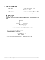
... pins 2 and 5 of the drawer kick-out solenoid must be as shown below: ON time (ON time + OFF time) ≤ 0.2 t Be sure to use the printer power supply (connector pin 4) for the drawer power source. 1-14 Features and General Specifications Rev.B t1 x 2 ms t2 x 2 ms Figure 1-9 Drawer kick-out drive signal...
... pins 2 and 5 of the drawer kick-out solenoid must be as shown below: ON time (ON time + OFF time) ≤ 0.2 t Be sure to use the printer power supply (connector pin 4) for the drawer power source. 1-14 Features and General Specifications Rev.B t1 x 2 ms t2 x 2 ms Figure 1-9 Drawer kick-out drive signal...
Technical Reference
Page 58
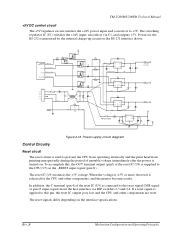
... To accomplish this pin, the reset IC output goes low and the CPU and other components, and the printer becomes ready. G R59 Q24 +5V Q27 Q1 D47 G N D Q2 D48 D6 P.G Q3 D49 ... GND 1 Figure 2-18 Power supply circuit diagram Control Circuitry Reset circuit The reset circuit is turned on. TM-U200D/U200PD Technical Manual +5V DC control circuit The +5V regulator circuit switches the +24V power input and converts...DIP switches 2-3 and 2-4. The reset signals differ depending on the RS-232 interface driver. The switching regulator IC (U1) switches the +24V input, smooths it to...
... To accomplish this pin, the reset IC output goes low and the CPU and other components, and the printer becomes ready. G R59 Q24 +5V Q27 Q1 D47 G N D Q2 D48 D6 P.G Q3 D49 ... GND 1 Figure 2-18 Power supply circuit diagram Control Circuitry Reset circuit The reset circuit is turned on. TM-U200D/U200PD Technical Manual +5V DC control circuit The +5V regulator circuit switches the +24V power input and converts...DIP switches 2-3 and 2-4. The reset signals differ depending on the RS-232 interface driver. The switching regulator IC (U1) switches the +24V input, smooths it to...
Technical Reference
Page 153
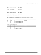
TM-U200D/U200PD Technical Manual "H" indicates: SD1 < SD2 RD1 < RD2 "L" indicates: SD1 > SD2 RD1 > RD2 The transmission data is H = 1, L = 0 Note: This format is used when the UART for RS-232 is high level Send data Rev. Printer reception data level RD1 RD2 Read data H L Receiving data line is low level L H Receiving data line is high level Printer transmission data level SD1 SD2 H L L H Sending data line is low level Sending data line is connected to the RS-485 driver. B Appendix A-5
TM-U200D/U200PD Technical Manual "H" indicates: SD1 < SD2 RD1 < RD2 "L" indicates: SD1 > SD2 RD1 > RD2 The transmission data is H = 1, L = 0 Note: This format is used when the UART for RS-232 is high level Send data Rev. Printer reception data level RD1 RD2 Read data H L Receiving data line is low level L H Receiving data line is high level Printer transmission data level SD1 SD2 H L L H Sending data line is low level Sending data line is connected to the RS-485 driver. B Appendix A-5


