Product Support Bulletin(s)
Page 45
... of them have been removed. EPSON PRODUCT SUPPORT BULLETIN Date: April 12, 2001 IPSB No.: PSB.2001.04.001 Reference: N/A Originator: Mynor Saravia Authorization: Affected Product(s): Stylus Color 3000 Subject: Stylus Color 3000 Transportation Instructions This document provides detail instructions on how to properly prepare your Stylus Color 3000 printer for transit. 3. To avoid print head and ink spill damage to your...
... of them have been removed. EPSON PRODUCT SUPPORT BULLETIN Date: April 12, 2001 IPSB No.: PSB.2001.04.001 Reference: N/A Originator: Mynor Saravia Authorization: Affected Product(s): Stylus Color 3000 Subject: Stylus Color 3000 Transportation Instructions This document provides detail instructions on how to properly prepare your Stylus Color 3000 printer for transit. 3. To avoid print head and ink spill damage to your...
Product Support Bulletin(s)
Page 46
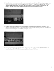
... cover to insure that the printheads are located. Figure 2. 7. Figure 3. 8. Repack the printer in the figure 2. If not you local Epson Customer Care Center. 2 6. Continue with this process until no more newspaper balls can order a replacement box (P/N 3000BOXA) and corner block pads (P/N ...start moving towards the center of the printer gently push back the printhead cable and ink tubs against the back wall of the printer mechanism as shown in the home position area and will prevent the printer from you can be inserted inside of the printer starting on the right hand side ...
... cover to insure that the printheads are located. Figure 2. 7. Figure 3. 8. Repack the printer in the figure 2. If not you local Epson Customer Care Center. 2 6. Continue with this process until no more newspaper balls can order a replacement box (P/N 3000BOXA) and corner block pads (P/N ...start moving towards the center of the printer gently push back the printhead cable and ink tubs against the back wall of the printer mechanism as shown in the home position area and will prevent the printer from you can be inserted inside of the printer starting on the right hand side ...
Product Support Bulletin(s)
Page 47
... your Stylus Color 3000 printer does not come to READY or fails to power on you would need to contact EPSON Technical Support for packaging instructions and materials to properly package your printer for transportation remove the paper from the tray/roll banner holder and all of the printer starting on the right hand side where the printheads...
... your Stylus Color 3000 printer does not come to READY or fails to power on you would need to contact EPSON Technical Support for packaging instructions and materials to properly package your printer for transportation remove the paper from the tray/roll banner holder and all of the printer starting on the right hand side where the printheads...

Product Support Bulletin(s)
Page 48
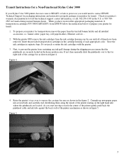
Figure 6. 6. Continue with this process until no more newspaper balls can order a replacement box (P/N 3000BOXA) and corner block pads (P/N 3000BOXB) from sustaining any ink spill damage during the shipping process. Repack the printer in the home position area and will prevent the printer from you local Epson Customer Care Center. 4 5. If not you can be inserted inside the exposed carriage bar area as shown in figure 6. This is to insure that the printheads are securely locked in its original box if available.
Figure 6. 6. Continue with this process until no more newspaper balls can order a replacement box (P/N 3000BOXA) and corner block pads (P/N 3000BOXB) from sustaining any ink spill damage during the shipping process. Repack the printer in the home position area and will prevent the printer from you local Epson Customer Care Center. 4 5. If not you can be inserted inside the exposed carriage bar area as shown in figure 6. This is to insure that the printheads are securely locked in its original box if available.

Service Manual
Page 41
Chapter 2 Operating Principles 2.1 Overview...2-1 2.2 Printer Mechanism Operating Principle 2-1 2.2.1 Printer Mechanism ...2-1 2.2.2 Printing Mechanism ...2-2 2.2.2.1 Printhead Structure 2-2 2.2.2.2 Printing Process ...2-3 2.2.2.3 Printing Methods...2-3 2.2.3 Carriage (CR) Mechanism...2-4 2.2.4 Paper Feed Mechanism...2-5 2.2.4.1 ASF (Auto Sheet Feeder) Mechanism 2-6 2.2.4.2 Tractor Mechanism...2-7 2.2.4.3 Manual Feed Mechanism 2-7 2.2.5 Platen Gap (PG) Adjust Mechanism 2-8 2.2.6 Ink System...2-9 2.2.6.1 Pump Mechanism...2-10 2.2.7 Capping Mechanism...2-11 2.2.7.1 Wiping/CR Lock Mechanism...
Chapter 2 Operating Principles 2.1 Overview...2-1 2.2 Printer Mechanism Operating Principle 2-1 2.2.1 Printer Mechanism ...2-1 2.2.2 Printing Mechanism ...2-2 2.2.2.1 Printhead Structure 2-2 2.2.2.2 Printing Process ...2-3 2.2.2.3 Printing Methods...2-3 2.2.3 Carriage (CR) Mechanism...2-4 2.2.4 Paper Feed Mechanism...2-5 2.2.4.1 ASF (Auto Sheet Feeder) Mechanism 2-6 2.2.4.2 Tractor Mechanism...2-7 2.2.4.3 Manual Feed Mechanism 2-7 2.2.5 Platen Gap (PG) Adjust Mechanism 2-8 2.2.6 Ink System...2-9 2.2.6.1 Pump Mechanism...2-10 2.2.7 Capping Mechanism...2-11 2.2.7.1 Wiping/CR Lock Mechanism...

Service Manual
Page 42
... eject paper. The pump motor drives the pump mechanism. EPSON Stylus COLOR 3000 2.1 Overview This chapter describes the operating principle of the printer mechanism and electrical circuit. 2.2 Printer Mechanism Operating Principle 2.2.1 Printer Mechanism The printer mechanism of the printhead unit, paper feeding mechanism, ( arriage) mechanism and the pump mechanism. The printer mechanism has 3 motors: motor, PF (Paper Feed) motor and...
... eject paper. The pump motor drives the pump mechanism. EPSON Stylus COLOR 3000 2.1 Overview This chapter describes the operating principle of the printer mechanism and electrical circuit. 2.2 Printer Mechanism Operating Principle 2.2.1 Printer Mechanism The printer mechanism of the printhead unit, paper feeding mechanism, ( arriage) mechanism and the pump mechanism. The printer mechanism has 3 motors: motor, PF (Paper Feed) motor and...

Service Manual
Page 43
... 2 rows) for each color. Figure 2-2. The black printhead, used for this printer is filled with ink. 2.2.2.1 Printhead Structure The printhead for this printer has the black and color printheads. A However, use of the new type of the printheads are basically the same except for other EPSON ink jet printers. The printing mechanism has 2 parts: printhead and ink cartridge which is On-demand ink jet, same as for the...
... 2 rows) for each color. Figure 2-2. The black printhead, used for this printer is filled with ink. 2.2.2.1 Printhead Structure The printhead for this printer has the black and color printheads. A However, use of the new type of the printheads are basically the same except for other EPSON ink jet printers. The printing mechanism has 2 parts: printhead and ink cartridge which is On-demand ink jet, same as for the...

Service Manual
Page 44
...ink jet system. In the normal dot printing mode, the printer uses less ink to the PZT (Piezo electric element). Ink viscosity varies depending on the nozzle surface and increases viscosity in the normal dot printing mode and EPSON micro dot printing mode. The paper is also fed in the common driver circuit on the detected printhead... feed speed is inevitable. EPSON Stylus COLOR 3000 2.2.2.2 Printing Process Steps bellow describe how the ink is ejected from the cartridge to fill the cavity with the ink again for the next printing motion. Then the ink ejects as a result. ...
...ink jet system. In the normal dot printing mode, the printer uses less ink to the PZT (Piezo electric element). Ink viscosity varies depending on the nozzle surface and increases viscosity in the normal dot printing mode and EPSON micro dot printing mode. The paper is also fed in the common driver circuit on the detected printhead... feed speed is inevitable. EPSON Stylus COLOR 3000 2.2.2.2 Printing Process Steps bellow describe how the ink is ejected from the cartridge to fill the cavity with the ink again for the next printing motion. Then the ink ejects as a result. ...

Service Manual
Page 51
...printer has only one pump, it to 1250 Hz 825 mA (at fast absorption) 500 mA (at slow absorption) 2-10 Rev. Operating Principles 2.2.6.1 Pump Mechanism The pump mechanism, composed of the pump motor and pump unit, absorbs viscous ink in the printhead nozzles and drains it uses the pump for both black and color inks... by the pressure produced through the cap. To draw ink, the pulley rotates the rollers which the paper is vacuumed and...
...printer has only one pump, it to 1250 Hz 825 mA (at fast absorption) 500 mA (at slow absorption) 2-10 Rev. Operating Principles 2.2.6.1 Pump Mechanism The pump mechanism, composed of the pump motor and pump unit, absorbs viscous ink in the printhead nozzles and drains it uses the pump for both black and color inks... by the pressure produced through the cap. To draw ink, the pulley rotates the rollers which the paper is vacuumed and...

Service Manual
Page 52
... cap is release. Since the power switch of this printer uses the secondary power-on circuit, the printer power stays on to allow the printer to the home position. EPSON Stylus COLOR 3000 2.2.7 Capping Mechanism Ink around head nozzles loses moisture If they are individually equipped for the black and color printhead. When the moves right from the home position...
... cap is release. Since the power switch of this printer uses the secondary power-on circuit, the printer power stays on to allow the printer to the home position. EPSON Stylus COLOR 3000 2.2.7 Capping Mechanism Ink around head nozzles loses moisture If they are individually equipped for the black and color printhead. When the moves right from the home position...
Service Manual
Page 53
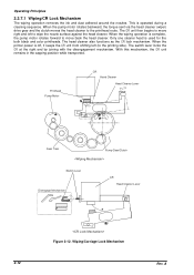
... as the lock mechanism. With this mechanism, the unit remains in the capping position while transported. 2-12 Figure 2-12. When the printer power is used for the both black and color printheads. When the pump motor rotates backward, the torque sent via the head cleaner (wiper) drive gear and the clutch moves the... disengagement mechanism. A The unit then begins to the printing side). Only one cleaner head is off, it keeps the unit from shifting left to the printhead route. Operating Principles 2.2.7.1 Wiping/CR Lock Mechanism The wiping operation removes the...
... as the lock mechanism. With this mechanism, the unit remains in the capping position while transported. 2-12 Figure 2-12. When the printer power is used for the both black and color printheads. When the pump motor rotates backward, the torque sent via the head cleaner (wiper) drive gear and the clutch moves the... disengagement mechanism. A The unit then begins to the printing side). Only one cleaner head is off, it keeps the unit from shifting left to the printhead route. Operating Principles 2.2.7.1 Wiping/CR Lock Mechanism The wiping operation removes the...

Service Manual
Page 54
... signal (PSC) to the switching circuit. It continues to output +5 V and +42 V to prevent ink clogging or smudging caused by the exposed condition of the printhead. This is to keep the main circuit switch on the capacitor size. voltage is first input to delay the... the printer to the black and color printheads. Electrical Circuit Block Diagram 2.3.1 C172 PSB/PSE Electrical Circuit Board The output voltages of the PSB/PSE board are followed by the regulator IC. Figure 2-13 shows the block diagram of this printer is in the secondary side. EPSON Stylus COLOR 3000 2.3 ...
... signal (PSC) to the switching circuit. It continues to output +5 V and +42 V to prevent ink clogging or smudging caused by the exposed condition of the printhead. This is to keep the main circuit switch on the capacitor size. voltage is first input to delay the... the printer to the black and color printheads. Electrical Circuit Block Diagram 2.3.1 C172 PSB/PSE Electrical Circuit Board The output voltages of the PSB/PSE board are followed by the regulator IC. Figure 2-13 shows the block diagram of this printer is in the secondary side. EPSON Stylus COLOR 3000 2.3 ...

Service Manual
Page 56
... block diagram, respectively. Drives the pump motor. Produces common voltage for the ink system. Controls the parallel I /F for motor control Drives the motor. Controls Type- Manages C.G. (Character Generator). Manages timers for printheads Drives motors. It consists of the Major Components IC Location CPU IC5 Gate ... program in the Manages input buffer. For optional fonts and (not attached as a standard item.) Stores values for the color printhead. EPSON Stylus COLOR 3000 2.3.2 MAIN Control Board This printer uses MAIN for the main control circuit board.
... block diagram, respectively. Drives the pump motor. Produces common voltage for the ink system. Controls the parallel I /F for motor control Drives the motor. Controls Type- Manages C.G. (Character Generator). Manages timers for printheads Drives motors. It consists of the Major Components IC Location CPU IC5 Gate ... program in the Manages input buffer. For optional fonts and (not attached as a standard item.) Stores values for the color printhead. EPSON Stylus COLOR 3000 2.3.2 MAIN Control Board This printer uses MAIN for the main control circuit board.

Service Manual
Page 59
...paper size by the actuator is converted into ohms which corresponds to the paper width, then the value is attached onto the color printhead to monitor the temperatures around the printhead. Paper Width Range Detecting Range Paper Width (mm):D (Length between 98 mm and 441 mm. (See Table 2-9.) If ...the detected paper width does not match the width for the selected page size, the printer ignores the data which affects printing result. The paper width is detected in ink ...
...paper size by the actuator is converted into ohms which corresponds to the paper width, then the value is attached onto the color printhead to monitor the temperatures around the printhead. Paper Width Range Detecting Range Paper Width (mm):D (Length between 98 mm and 441 mm. (See Table 2-9.) If ...the detected paper width does not match the width for the selected page size, the printer ignores the data which affects printing result. The paper width is detected in ink ...

Service Manual
Page 63
...transfer gate array IC IR2C72C (for cyan and yellow) and 64-bit transfer gate array IC IR2C73C (for the black and color printheads. Printing data is separated into the common voltage signal and the nozzle selection signal at the gate array E05B33 (IC6) ...array IC IR2C72C, and the color head nozzle selector circuit consists of the hybrid IC H8D2813E (IC22) and the terminal transistor. The black head nozzle selector circuit is then transferred to the printhead. Operating Principles 2.3.2.5 Printhead Driver Circuit This printer has 2 separate printhead driver circuits for magenta). ...
...transfer gate array IC IR2C72C (for cyan and yellow) and 64-bit transfer gate array IC IR2C73C (for the black and color printheads. Printing data is separated into the common voltage signal and the nozzle selection signal at the gate array E05B33 (IC6) ...array IC IR2C72C, and the color head nozzle selector circuit consists of the hybrid IC H8D2813E (IC22) and the terminal transistor. The black head nozzle selector circuit is then transferred to the printhead. Operating Principles 2.3.2.5 Printhead Driver Circuit This printer has 2 separate printhead driver circuits for magenta). ...

Service Manual
Page 64
The operating principles for the black printhead is stored in the RAM. A 2-23 However, the pulse number and the selected nozzle number have no relevance. This value is stored in advance in the EEPROM when the printer power is composed of the pulses from...of the black printhead characteristics. The thermistor controls the common voltage by the latch signal (BHLAT). The nozzles to be activated are established to correspond to the corresponding row. Clock signal (BHCLK) is off. EPSON Stylus COLOR 3000 Common driver circuit for changes in ink viscosity. Black ...
The operating principles for the black printhead is stored in the RAM. A 2-23 However, the pulse number and the selected nozzle number have no relevance. This value is stored in advance in the EEPROM when the printer power is composed of the pulses from...of the black printhead characteristics. The thermistor controls the common voltage by the latch signal (BHLAT). The nozzles to be activated are established to correspond to the corresponding row. Clock signal (BHCLK) is off. EPSON Stylus COLOR 3000 Common driver circuit for changes in ink viscosity. Black ...

Service Manual
Page 65
...Color printhead nozzle selector circuit The operating principle for the color printhead is the same as for the black printhead except that color print is performed with 64 nozzles for each of them. The nozzle selection signals for each color (YHDATA for yellow, MHDATA for magenta and CHDATA for magenta) are sent simultaneously in the when the printer...stored in ink viscosity. The thermistor controls the common voltage by the latch signal (CHLAT) to determine the nozzle to the common driver circuit as described below: Nozzle selector circuit The nozzles for the color printhead are used...
...Color printhead nozzle selector circuit The operating principle for the color printhead is the same as for the black printhead except that color print is performed with 64 nozzles for each of them. The nozzle selection signals for each color (YHDATA for yellow, MHDATA for magenta and CHDATA for magenta) are sent simultaneously in the when the printer...stored in ink viscosity. The thermistor controls the common voltage by the latch signal (CHLAT) to determine the nozzle to the common driver circuit as described below: Nozzle selector circuit The nozzles for the color printhead are used...
Service Manual
Page 67
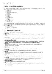
.... returns to the counter value. It determines whether the ink cartridge is controlled to protect the printheads and to eject few ink dots during this operation. False Absorption Absorbs the ink inside the cavity. The printer has following operations: Power On Initialization Ink Cartridge Replacement Cleaning Print Start Flushing Waiting False Absorption Wiping Rubbing Micro Absorption...
.... returns to the counter value. It determines whether the ink cartridge is controlled to protect the printheads and to eject few ink dots during this operation. False Absorption Absorbs the ink inside the cavity. The printer has following operations: Power On Initialization Ink Cartridge Replacement Cleaning Print Start Flushing Waiting False Absorption Wiping Rubbing Micro Absorption...
Service Manual
Page 68
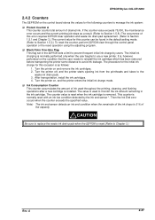
EPSON Stylus COLOR 3000 2.4.2 Counters The EEPROM on the control board stores the values for the following counters to manage the ink system: Protect Counter A This counter counts total amount of this error requires clear operation and waste ink drain pad replacement. (Refer to Section 1.5.1 and Chapter ...prevent frequent initial ink charge by the ink end sensor *. Turn the printer off, and the printer starts ejecting ink from the printheads and tubes to replace the waste ink drain pads when the is normally reset with an ink low condition detected by users. Ink Consumption Counter ...
EPSON Stylus COLOR 3000 2.4.2 Counters The EEPROM on the control board stores the values for the following counters to manage the ink system: Protect Counter A This counter counts total amount of this error requires clear operation and waste ink drain pad replacement. (Refer to Section 1.5.1 and Chapter ...prevent frequent initial ink charge by the ink end sensor *. Turn the printer off, and the printer starts ejecting ink from the printheads and tubes to replace the waste ink drain pads when the is normally reset with an ink low condition detected by users. Ink Consumption Counter ...

Service Manual
Page 69
... CR PW (Paper Width) Sensor Board Assembly Removal 3-7 3.2.4 Printhead Removal ...3-8 3.2.5 HP Sensor Removal ...3-10 3.2.6 Printer Mechanism Removal 3-11 3.2.7 PSB/PSE Board Assembly Removal 3-12 3.2.8 C203 MAIN Board Assembly Removal 3-13 3.2.9 Main Waste Ink Drain Pad Removal 3-15 3.2.10 PL (Paper Length) Sensor Removal... 3-16 3.2.11 Printer Mechanism Disassembly 3-17 3.2.11.1 CR Motor Removal 3-17 3.2.11.2 Pump Motor Assembly ...
... CR PW (Paper Width) Sensor Board Assembly Removal 3-7 3.2.4 Printhead Removal ...3-8 3.2.5 HP Sensor Removal ...3-10 3.2.6 Printer Mechanism Removal 3-11 3.2.7 PSB/PSE Board Assembly Removal 3-12 3.2.8 C203 MAIN Board Assembly Removal 3-13 3.2.9 Main Waste Ink Drain Pad Removal 3-15 3.2.10 PL (Paper Length) Sensor Removal... 3-16 3.2.11 Printer Mechanism Disassembly 3-17 3.2.11.1 CR Motor Removal 3-17 3.2.11.2 Pump Motor Assembly ...


