Installation Manual
Page 4
...limits the horizontal rotation of the stopper. Product may cause equipment damage and fire. ❏ Be sure to set this equipment on top of this manual. EMC and Safety Standards Applied Product Name: DM-D210 Type Name: M59DB The following standards are applied only to the display that is so labeled. (EMC is tested using the EPSON PS-170 power... to force it falls. ❏ Do not attach plural extension supports. Equipment may damage the equipment. CAUTION: ❏ Do not plug the cable differently from the instruction in locations subject to high humidity or dust levels.
...limits the horizontal rotation of the stopper. Product may cause equipment damage and fire. ❏ Be sure to set this equipment on top of this manual. EMC and Safety Standards Applied Product Name: DM-D210 Type Name: M59DB The following standards are applied only to the display that is so labeled. (EMC is tested using the EPSON PS-170 power... to force it falls. ❏ Do not attach plural extension supports. Equipment may damage the equipment. CAUTION: ❏ Do not plug the cable differently from the instruction in locations subject to high humidity or dust levels.

Installation Manual
Page 6
...-U675 15 Attaching to Other TM Printers 20 Attaching to the DM-D stand 23 Part Names and Functions 30 Exterior 30 DIP Switch 31 DIP Switch Functions 31 Turning and Tilting the DM-D210 33 Self Test 34 Check Items of Self test 34 Performing Self test 34 Diagnostics 34 Specification 35 General Specifications 35 Electrical Specifications 38 Environmental Specifications 38 Character Specifications 39 Reliability Specification 39 4
...-U675 15 Attaching to Other TM Printers 20 Attaching to the DM-D stand 23 Part Names and Functions 30 Exterior 30 DIP Switch 31 DIP Switch Functions 31 Turning and Tilting the DM-D210 33 Self Test 34 Check Items of Self test 34 Performing Self test 34 Diagnostics 34 Specification 35 General Specifications 35 Electrical Specifications 38 Environmental Specifications 38 Character Specifications 39 Reliability Specification 39 4
Installation Manual
Page 7
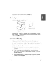
... DM-D210 and printers connected to the DMD210 are in vacuum fluorescent display. 5 If you may damage the built-in the box. English This manual explains how to note the following items are turned off. ❏ Do not drop the DM-D210, because you find anything missing or damaged items, please contact your DM-D210 dealer. Cautions on Handling When you use the DM-D210, be sure to set...
... DM-D210 and printers connected to the DMD210 are in vacuum fluorescent display. 5 If you may damage the built-in the box. English This manual explains how to note the following items are turned off. ❏ Do not drop the DM-D210, because you find anything missing or damaged items, please contact your DM-D210 dealer. Cautions on Handling When you use the DM-D210, be sure to set...
Installation Manual
Page 8
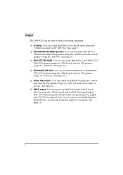
... to extend the length of the DM-D210, an optional extension support is required. Usage The DM-D210 can attach the DM-D210 to TM-H6000/ TM-U675 printers using the "DM-D pole unit for TM printers (Type A)" (DP-502). (See page 15.) ❏ Other TM printers. You can attach the DM-D210 using the "DM-D pole unit for TM printers (Type A)" (DP-502) and Velcro tapes or screws. (See page 20...
... to extend the length of the DM-D210, an optional extension support is required. Usage The DM-D210 can attach the DM-D210 to TM-H6000/ TM-U675 printers using the "DM-D pole unit for TM printers (Type A)" (DP-502). (See page 15.) ❏ Other TM printers. You can attach the DM-D210 using the "DM-D pole unit for TM printers (Type A)" (DP-502) and Velcro tapes or screws. (See page 20...

Installation Manual
Page 9
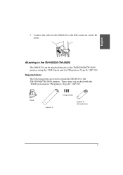
... you feel it click. Pass the cable for the DM-D210 through support A, and attach support A to the IR series. When using the "DM-D pole unit for extension) Assembling steps 1. These items are used to attach the DM-D210 to the DM-D210. When using support B for IR" (DP-504). Required items The following items are packed with the "DM-D pole unit for extension 7 base fixing screws support A support B (for IR" (DP-504).
... you feel it click. Pass the cable for the DM-D210 through support A, and attach support A to the IR series. When using the "DM-D pole unit for extension) Assembling steps 1. These items are used to attach the DM-D210 to the DM-D210. When using support B for IR" (DP-504). Required items The following items are packed with the "DM-D pole unit for extension 7 base fixing screws support A support B (for IR" (DP-504).
Installation Manual
Page 11
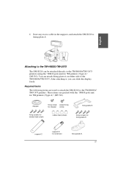
Attaching to the TM-H5000II/TM-J8000 The DM-D210 can be attached directly to the DM connector on the IR series. base support C fixing screws support B (for TM printers (Type B)" (DP-503). These items are used to attach the DM-D210 to the TM-H5000II/TM-J8000 printers. Connect the cable for the DM-D210 to the TM-H5000II/TM-J8000 printers using the "DM-D pole unit for TM printers (Type B)" (DP-503). Required items The following items are packed with the "DM-D pole unit for extension) 9 English 5.
Attaching to the TM-H5000II/TM-J8000 The DM-D210 can be attached directly to the DM connector on the IR series. base support C fixing screws support B (for TM printers (Type B)" (DP-503). These items are used to attach the DM-D210 to the TM-H5000II/TM-J8000 printers. Connect the cable for the DM-D210 to the TM-H5000II/TM-J8000 printers using the "DM-D pole unit for TM printers (Type B)" (DP-503). Required items The following items are packed with the "DM-D pole unit for extension) 9 English 5.
Installation Manual
Page 12
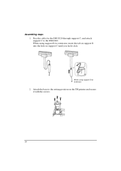
Pass the cable for the DM-D210 through support C, and attach support C to the setting position on support C until you feel it with the screws. 10 When using support B for extension, insert the tab on support B into the hole on the TM printer and secure it click. When using support B for extension 2. Attach the base to the DM-D210. Assembling steps 1.
Pass the cable for the DM-D210 through support C, and attach support C to the setting position on support C until you feel it with the screws. 10 When using support B for extension, insert the tab on support B into the hole on the TM printer and secure it click. When using support B for extension 2. Attach the base to the DM-D210. Assembling steps 1.
Installation Manual
Page 17
... fixing plate A. 6. Required items The following items are packed with the "DM-D pole unit for extension fixing plate A 15 stopper fixing screw angle fixing for stopper screw fixing screws for rubber feet (small) rubber feet (small) fixing plate B fixing screws for fixing plate B support C support B for TM printers (Type A)" (DP-502). Store any excess cable in the support, and attach the DM-D210 to the TM-H6000/ TM-U675 printers. English...
... fixing plate A. 6. Required items The following items are packed with the "DM-D pole unit for extension fixing plate A 15 stopper fixing screw angle fixing for stopper screw fixing screws for rubber feet (small) rubber feet (small) fixing plate B fixing screws for fixing plate B support C support B for TM printers (Type A)" (DP-502). Store any excess cable in the support, and attach the DM-D210 to the TM-H6000/ TM-U675 printers. English...
Installation Manual
Page 21
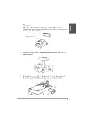
paper roll cover 8. Store any excess cable in the support and attach the DM-D210 to the tabs on fixing plate B, as shown below. 19 To avoid disconnection, hook the cable to fixing plate A. 9. Connect the power cable of the display, make sure that you can open if the position of the display is inappropriate. Before securing the position of the printer. English Note: The paper roll cover may not open the paper roll cover.
paper roll cover 8. Store any excess cable in the support and attach the DM-D210 to the tabs on fixing plate B, as shown below. 19 To avoid disconnection, hook the cable to fixing plate A. 9. Connect the power cable of the display, make sure that you can open if the position of the display is inappropriate. Before securing the position of the printer. English Note: The paper roll cover may not open the paper roll cover.

Installation Manual
Page 24
Follow steps 2 and 3 in the support, and attach the DM-D210 to the setting position with fixing screws. 3. Attach the DM-D210 to the setting position. Peel off the Velcro tapes, and attach the display to fixing plate A. 22 Assembling steps using Velcro tapes." 2. Secure fixing plate A to fixing plate A. 6. Store any excess cable in "Assembling steps using screws 1. 5.
Follow steps 2 and 3 in the support, and attach the DM-D210 to the setting position with fixing screws. 3. Attach the DM-D210 to the setting position. Peel off the Velcro tapes, and attach the display to fixing plate A. 22 Assembling steps using Velcro tapes." 2. Secure fixing plate A to fixing plate A. 6. Store any excess cable in "Assembling steps using screws 1. 5.

Installation Manual
Page 25
... installation screw (mm type) power supply unit AC cable 23 If DM-D210 you want to the DM-D stand. The DM-D210 with the DM-D stand can be attached directly to a TM printer, or be connected to the DM-D stand using the DM-D stand. Please get them separately from the DM-D stand unit (DP-501). DM-D stand extension cable for DM Customer Display " (DP-210). English Attaching to the DM-D stand The DM-D210...
... installation screw (mm type) power supply unit AC cable 23 If DM-D210 you want to the DM-D stand. The DM-D210 with the DM-D stand can be attached directly to a TM printer, or be connected to the DM-D stand using the DM-D stand. Please get them separately from the DM-D stand unit (DP-501). DM-D stand extension cable for DM Customer Display " (DP-210). English Attaching to the DM-D stand The DM-D210...
Installation Manual
Page 27
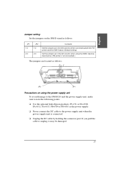
... part. English Jumper setting Set the jumpers on the DM-D stand as follows: JP1 1-2 2-3 JP2 1-2 2-3 Contents Set the jumpers as in the left columns when connecting both the TM printer and the DM-D stand. (Default setting) Set the jumpers as in the left column when using the power supply unit To avoid damage to the DM-D210 and the power supply unit, make sure to note the following points. ❏ Use...
... part. English Jumper setting Set the jumpers on the DM-D stand as follows: JP1 1-2 2-3 JP2 1-2 2-3 Contents Set the jumpers as in the left columns when connecting both the TM printer and the DM-D stand. (Default setting) Set the jumpers as in the left column when using the power supply unit To avoid damage to the DM-D210 and the power supply unit, make sure to note the following points. ❏ Use...

Installation Manual
Page 29
Connect one end of the cables to the RS-232 connector on the DM-D stand; then connect the other end to fasten them. 27 English 3. Tighten the screws on the DM-D stand until you feel it click. 4. Connect the cable for the DM-D210 to the display connector on both ends of the computer interface cable to the computer connector on the computer.
Connect one end of the cables to the RS-232 connector on the DM-D stand; then connect the other end to fasten them. 27 English 3. Tighten the screws on the DM-D stand until you feel it click. 4. Connect the cable for the DM-D210 to the display connector on both ends of the computer interface cable to the computer connector on the computer.

Installation Manual
Page 32
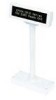
Part Names and Functions Exterior display power switch (bottom of the display) DIP switch (bottom of the display) ❏ Display: Characters are displayed. ❏ Power switch: The power is turned on/off. ❏ DIP switch: The functions of the DM-D210 are changed. (See "DIP switch" for details.) Note: When turning on the DM-D210 again after turning it off, wait for at least 3 seconds. 30
Part Names and Functions Exterior display power switch (bottom of the display) DIP switch (bottom of the display) ❏ Display: Characters are displayed. ❏ Power switch: The power is turned on/off. ❏ DIP switch: The functions of the DM-D210 are changed. (See "DIP switch" for details.) Note: When turning on the DM-D210 again after turning it off, wait for at least 3 seconds. 30

Installation Manual
Page 33
... not perform Default setting OFF OFF OFF OFF ON OFF ON OFF (*)This function can select whether or not you perform self test when turning on or off Parity type Change transmission speed Self test selection (*) ON Ignored 7 bits Parity Even OFF Displays "?" 8 bits No parity Odd See "Transmission speed." English DIP Switch DIP Switch Functions The DM-D210 has one...
... not perform Default setting OFF OFF OFF OFF ON OFF ON OFF (*)This function can select whether or not you perform self test when turning on or off Parity type Change transmission speed Self test selection (*) ON Ignored 7 bits Parity Even OFF Displays "?" 8 bits No parity Odd See "Transmission speed." English DIP Switch DIP Switch Functions The DM-D210 has one...

Installation Manual
Page 35
English Turning and Tilting the DM-D210 You can be moved easily, so do not move it by force, you desire, and reattach it to the direction you may damage it stops. In this case, remove the base, change the position of the tab ob the base so that the display faces ... 4 positions) ❏ Horizontal rotation: 330° max. 33 If you move any further if it . With the "DM-D pole unit for IR" (DP-504) and the "DM-D pole unit for TM printers (Type B)" (DP-503), the display area maynot face the direction you desire. The display can turn or tilt the display while holding the support.
English Turning and Tilting the DM-D210 You can be moved easily, so do not move it by force, you desire, and reattach it to the direction you may damage it stops. In this case, remove the base, change the position of the tab ob the base so that the display faces ... 4 positions) ❏ Horizontal rotation: 330° max. 33 If you move any further if it . With the "DM-D pole unit for IR" (DP-504) and the "DM-D pole unit for TM printers (Type B)" (DP-503), the display area maynot face the direction you desire. The display can turn or tilt the display while holding the support.

Installation Manual
Page 36
... following items are not displayed, the DM-D210 may be malfunctioning. Please contact your DM-D210 dealer for the DM-D210. 2. Note: If the contents of the self test are checked during the self test: ❏ Control ROM version ❏ DIP switch settings ❏ Memory switch settings ❏ Example of display characters ❏ Example of the DIP switch settings. When an error is detected, the error message is displayed...
... following items are not displayed, the DM-D210 may be malfunctioning. Please contact your DM-D210 dealer for the DM-D210. 2. Note: If the contents of the self test are checked during the self test: ❏ Control ROM version ❏ DIP switch settings ❏ Memory switch settings ❏ Example of display characters ❏ Example of the DIP switch settings. When an error is detected, the error message is displayed...

Installation Manual
Page 39
... Weight: 116 g • Fixing plate A and support C of the "DM-D pole unit for TM printers (Type A)" (DP-502): Height: 260 mm Width: 78 mm Depth: 164 mm Weight: 264 g ❏ Tilt angle Max 36° (3 steps, 4 positions) ❏ Horizontal rotation Max 330° ❏ Vacuum fluorescent display • Number of characters: 20 column × 2 lines max. (When using Font B) • Display color: • Brightness...
... Weight: 116 g • Fixing plate A and support C of the "DM-D pole unit for TM printers (Type A)" (DP-502): Height: 260 mm Width: 78 mm Depth: 164 mm Weight: 264 g ❏ Tilt angle Max 36° (3 steps, 4 positions) ❏ Horizontal rotation Max 330° ❏ Vacuum fluorescent display • Number of characters: 20 column × 2 lines max. (When using Font B) • Display color: • Brightness...

Installation Manual
Page 40
Electrical Specifications ❏ Type PS-170, PA-6508, PB-6509, PB-6510, PA-6511, PA-6513 (when using the DM-D stand) ❏ Rated voltage DC 11.4 to 48 V ❏ Rated current 0.4 A (max.) Environmental Specifications ❏ Operation environment Temperature: 5°C to 40°C Humidity: 30% to 85% (No condensation) ❏ Storage environment Temperature: −10°C to 50°C Humidity: 30% to 90% (No condensation) 38
Electrical Specifications ❏ Type PS-170, PA-6508, PB-6509, PB-6510, PA-6511, PA-6513 (when using the DM-D stand) ❏ Rated voltage DC 11.4 to 48 V ❏ Rated current 0.4 A (max.) Environmental Specifications ❏ Operation environment Temperature: 5°C to 40°C Humidity: 30% to 85% (No condensation) ❏ Storage environment Temperature: −10°C to 50°C Humidity: 30% to 90% (No condensation) 38

Installation Manual
Page 41
English Character Specifications ❏ Type of character • Alphanumeric characters: 95 • International characters: 37 • Extended graphics: 128 characters × 12 pages ❏ Character grid • Font : • Character size • Character pitch 5 × 7 dot, comma, period, annunciator 3.5 mm x 5.0 mm 9.9 mm Reliability Specification ❏ MTBF (vacuum fluorescent display only) 20,000 hours (a half-value period of the brightness) 39
English Character Specifications ❏ Type of character • Alphanumeric characters: 95 • International characters: 37 • Extended graphics: 128 characters × 12 pages ❏ Character grid • Font : • Character size • Character pitch 5 × 7 dot, comma, period, annunciator 3.5 mm x 5.0 mm 9.9 mm Reliability Specification ❏ MTBF (vacuum fluorescent display only) 20,000 hours (a half-value period of the brightness) 39


