
User Manual
Page 3
... attached power cord be specified in the radii interference regulations of the Canadian Department of the following measures: • Reorient or relocate the receiving antenna. • Increase the separation between the equipment and receiver. • Connect the equipment into an outlet on , the user is required in a particular installation. If this computer. Use only shielded cables to connect I/O devices...
... attached power cord be specified in the radii interference regulations of the Canadian Department of the following measures: • Reorient or relocate the receiving antenna. • Increase the separation between the equipment and receiver. • Connect the equipment into an outlet on , the user is required in a particular installation. If this computer. Use only shielded cables to connect I/O devices...

User Manual
Page 5
...", shows you the basics of your system and shows you 'll find in this manual: Chapter 1- Chapter 3 - 'Operating Your System: shows you how to install disk drives. Chapter 6 - About This Manual What's Inside Here's what you how to set up or upgrade your system. Chapter 5 - "Glossary": explains some technical specifications for additional help. Chapter 2 - "Keyboard", explains the keyboards features, layout and basic functions. Chapter 7 -
...", shows you the basics of your system and shows you 'll find in this manual: Chapter 1- Chapter 3 - 'Operating Your System: shows you how to install disk drives. Chapter 6 - About This Manual What's Inside Here's what you how to set up or upgrade your system. Chapter 5 - "Glossary": explains some technical specifications for additional help. Chapter 2 - "Keyboard", explains the keyboards features, layout and basic functions. Chapter 7 -

User Manual
Page 7
Contents Chapter 1 System Overview 1 1-1 Introduction 2 Operating System 2 1-2 QuickStart 3 1-3 Features 4 1-4 Specifications 5 1-5 Example of a System Configuration 6 1-6 SystemUnit 7 1-7 Control Panel 8 Reset Button 8 Turbo Button 8 Indicator Lights 8 Keylock 8 System Power Switch 9 1-8 Rear Panel 10 Keyboard Connector 11 Power Cord Connector 12 Display Port 13 Power Voltage Setting 14 1-9 Other Peripherals 16 1-10 Disk Drives 17 Floppy Disk Drives 18 Copy Protection 19 Hard Disks 2 0 1-11 Keyboard 21 1-12 Maintaining Your Equipment 22 vi
Contents Chapter 1 System Overview 1 1-1 Introduction 2 Operating System 2 1-2 QuickStart 3 1-3 Features 4 1-4 Specifications 5 1-5 Example of a System Configuration 6 1-6 SystemUnit 7 1-7 Control Panel 8 Reset Button 8 Turbo Button 8 Indicator Lights 8 Keylock 8 System Power Switch 9 1-8 Rear Panel 10 Keyboard Connector 11 Power Cord Connector 12 Display Port 13 Power Voltage Setting 14 1-9 Other Peripherals 16 1-10 Disk Drives 17 Floppy Disk Drives 18 Copy Protection 19 Hard Disks 2 0 1-11 Keyboard 21 1-12 Maintaining Your Equipment 22 vi

User Manual
Page 11
... 1-2: System Configuration 6 Figure 1-3: System Unit Case 7 Figure 1-4: Front Panel 8 Figure 1-5: Keylock and Two Security-lock Keys 9 Figure 1-6: Rear Panel 1 0 Figure 1-7: Connecting the Keyboard Cable 11 Figure 1-8: System Power Cord 12 Figure 1-9: Two Kinds of Display Connectors 13 Figure 1-10: Voltage Switch 14 Figure 1-11: Power Cord Specifications 15 Figure 1-12: System Unit Connected to Peripherals 16 Figure 1-13: Installing Floppy and Hard Disk Drives 17 Figure 1-14: Floppy Disk Specifications 18 Figure...
... 1-2: System Configuration 6 Figure 1-3: System Unit Case 7 Figure 1-4: Front Panel 8 Figure 1-5: Keylock and Two Security-lock Keys 9 Figure 1-6: Rear Panel 1 0 Figure 1-7: Connecting the Keyboard Cable 11 Figure 1-8: System Power Cord 12 Figure 1-9: Two Kinds of Display Connectors 13 Figure 1-10: Voltage Switch 14 Figure 1-11: Power Cord Specifications 15 Figure 1-12: System Unit Connected to Peripherals 16 Figure 1-13: Installing Floppy and Hard Disk Drives 17 Figure 1-14: Floppy Disk Specifications 18 Figure...
User Manual
Page 35
... repair the system unit, monitor/s, cables/wires. Refer all such problems to qualified technician. 22 Chapter 1: System Overview Ensure that all ventilation outlets are always free from obstruction. In the event of the system unit is equipped with a 3-wire grounding-type plug. 1-12 Maintaining Your Equipment Read and follow carefully all the instructions and warnings in this product yourself, as opening and removing covers...
... repair the system unit, monitor/s, cables/wires. Refer all such problems to qualified technician. 22 Chapter 1: System Overview Ensure that all ventilation outlets are always free from obstruction. In the event of the system unit is equipped with a 3-wire grounding-type plug. 1-12 Maintaining Your Equipment Read and follow carefully all the instructions and warnings in this product yourself, as opening and removing covers...

User Manual
Page 46
...-pin jumper in ascending order. 10 Chapter 2: Setting Up Your System 2-3 Jumper Options and Connectors After the switches are set correctly, other attachments and jumper option adjustments on the function of the board while it keeps the cap handy. See the illustration on page 4 for the system configuration you should save the cap for future use by covering only one pin of the jumper. If a jumper needs to connect...
...-pin jumper in ascending order. 10 Chapter 2: Setting Up Your System 2-3 Jumper Options and Connectors After the switches are set correctly, other attachments and jumper option adjustments on the function of the board while it keeps the cap handy. See the illustration on page 4 for the system configuration you should save the cap for future use by covering only one pin of the jumper. If a jumper needs to connect...

User Manual
Page 56
... and manage files on your MS-DOS User's Guide and Reference manual for Disk Operating System. Starting DOS from your hard disk: lf you start DOS. Loading DOS Loading DOS means to copy all the DOS programs into disk drive A and close the drive lever. • Press the reset button on your front panel (hardware reset) or hold down the , and keys at the same time (software reset) to reboot your disk drive when...
... and manage files on your MS-DOS User's Guide and Reference manual for Disk Operating System. Starting DOS from your hard disk: lf you start DOS. Loading DOS Loading DOS means to copy all the DOS programs into disk drive A and close the drive lever. • Press the reset button on your front panel (hardware reset) or hold down the , and keys at the same time (software reset) to reboot your disk drive when...

User Manual
Page 60
... your disk after the RAM test to enter the SETUP program. To format a hard disk drive, you can be set up on your computer, you can use creating DOS partition, see Chapter 6: Managing Disks in MS-DOS User's Guide and Reference. Preformatting The preformat utility is the first operating system to be read from or written to. Choose item 2 from the initial screen to preformat a hard disk. The "FDISK" command displays a serial...
... your disk after the RAM test to enter the SETUP program. To format a hard disk drive, you can be set up on your computer, you can use creating DOS partition, see Chapter 6: Managing Disks in MS-DOS User's Guide and Reference. Preformatting The preformat utility is the first operating system to be read from or written to. Choose item 2 from the initial screen to preformat a hard disk. The "FDISK" command displays a serial...
User Manual
Page 64
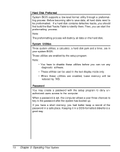
... to deny unauthorized users access to identify them. Keeping it in your system BIOS. Before becoming able to save data, all hard disks need to be used in the password after the system has booted up. Note: • You have a short memory, you can run any diagnostic software. • These utilities can start the preformatting process. If you have to key in the text display mode only. •...
... to deny unauthorized users access to identify them. Keeping it in your system BIOS. Before becoming able to save data, all hard disks need to be used in the password after the system has booted up. Note: • You have a short memory, you can run any diagnostic software. • These utilities can start the preformatting process. If you have to key in the text display mode only. •...
User Manual
Page 65
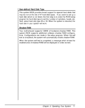
... RAM configurations. When the system is completed, the system will automatically enable shadow RAM. When the system self test is completed, a message which is not listed, the first step is to enter the ROM setup program for special hard disks that may be displayed on the list of hardware shadow RAM. User-defined Hard Disk Type This system BIOS provides broad support for hard disk type to set the number of shadow RAM will be not on video screen...
... RAM configurations. When the system is completed, the system will automatically enable shadow RAM. When the system self test is completed, a message which is not listed, the first step is to enter the ROM setup program for special hard disks that may be displayed on the list of hardware shadow RAM. User-defined Hard Disk Type This system BIOS provides broad support for hard disk type to set the number of shadow RAM will be not on video screen...

User Manual
Page 66
... key to enter the setup program or press any other key to continue Under the above conditions, pressing will start the setup program. Pressing , to Enter the Setup Program You will have to reconfigure your computer is turned on the screen as they appear. 3-7 Setup Program A system setup program included in your BIOS is used to set the date, time, base memory, extended memory, number of floppy/hard disk drives and display configuration...
... key to enter the setup program or press any other key to continue Under the above conditions, pressing will start the setup program. Pressing , to Enter the Setup Program You will have to reconfigure your computer is turned on the screen as they appear. 3-7 Setup Program A system setup program included in your BIOS is used to set the date, time, base memory, extended memory, number of floppy/hard disk drives and display configuration...

User Manual
Page 71
... drive types (1-47) match your fixed disk drive specifications you have one) on which your system, you finish keying in the password after the system has been booted up shadow RAM, you may exit the setup program by choosing item 9. lf you disable the password function, the setup program will ask you to configure a userdefined hard disk type. If you want to key in these numbers, this user-defined option may use...
... drive types (1-47) match your fixed disk drive specifications you have one) on which your system, you finish keying in the password after the system has been booted up shadow RAM, you may exit the setup program by choosing item 9. lf you disable the password function, the setup program will ask you to configure a userdefined hard disk type. If you want to key in these numbers, this user-defined option may use...

User Manual
Page 89
... a copy of these parts with floppy disk drives. You may need to replace your system unit and check whether the speaker on the inside of problems with parts that the power cable from the power supply to the floppy disk drive is in good working , stop what is connected firmly to the motherboard. System Does Not Beep after Startup If you have either of the screen by using the + key combination. Other Suggestions...
... a copy of these parts with floppy disk drives. You may need to replace your system unit and check whether the speaker on the inside of problems with parts that the power cable from the power supply to the floppy disk drive is in good working , stop what is connected firmly to the motherboard. System Does Not Beep after Startup If you have either of the screen by using the + key combination. Other Suggestions...
User Manual
Page 90
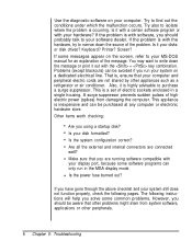
... isolate where the problem is , ensure that you using a startup disk? Is it is a set of electric sockets enclosed in the MGA display mode. Is it out with your hardware? Also, it with a certain software program or with the + key combination. Other items worth checking: Are you are connected well? Are all the external and internal connectors are running software compatible with software, you run in a single housing...
... isolate where the problem is , ensure that you using a startup disk? Is it is a set of electric sockets enclosed in the MGA display mode. Is it out with your hardware? Also, it with a certain software program or with the + key combination. Other items worth checking: Are you are connected well? Are all the external and internal connectors are running software compatible with software, you run in a single housing...

User Manual
Page 96
The power cable is simple to connect: simply plug it in to the correct adapter. Chapter 6: Appendix 3 • Slide the disk drive, back end first, into the disk drive bay. The shape of the four cables from the power supply. Figure 6-2: Installing the Floppy and Hard Disk Drives • Next, connect the floppy/hard disk controller cable and one of the plug ensures that no mistakes will be made.
The power cable is simple to connect: simply plug it in to the correct adapter. Chapter 6: Appendix 3 • Slide the disk drive, back end first, into the disk drive bay. The shape of the four cables from the power supply. Figure 6-2: Installing the Floppy and Hard Disk Drives • Next, connect the floppy/hard disk controller cable and one of the plug ensures that no mistakes will be made.

User Manual
Page 99
Refer to that for a floppy disk drive. • First fasten the bracket on a Hard Disk Drive • Next, place the disk drive inside the bay and fasten the brackets to the chassis. Hard Disk Drives The installation of a hard disk drive is similar to Figure 6-2. 6 Chapter 6: Appendix Figure 6-6: Fasten the Brackets on the drive.
Refer to that for a floppy disk drive. • First fasten the bracket on a Hard Disk Drive • Next, place the disk drive inside the bay and fasten the brackets to the chassis. Hard Disk Drives The installation of a hard disk drive is similar to Figure 6-2. 6 Chapter 6: Appendix Figure 6-6: Fasten the Brackets on the drive.
User Manual
Page 102
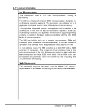
... in features to support operating systems. In addition, its object code is the natural environment of paging and I/O-permission bit mapping. The 386 is a high-performance 32-bit microprocessor designed for multitasking operating systems. The processor can be isolated and protected from one another by use of the 386. 6-2 Technical lnformation 386 Microprocessor The mainboard uses a 386-33/40 microprocessor running at 33/40MHz...
... in features to support operating systems. In addition, its object code is the natural environment of paging and I/O-permission bit mapping. The 386 is a high-performance 32-bit microprocessor designed for multitasking operating systems. The processor can be isolated and protected from one another by use of the 386. 6-2 Technical lnformation 386 Microprocessor The mainboard uses a 386-33/40 microprocessor running at 33/40MHz...

User Manual
Page 105
... enable 1 Data bit 6 0 Enable video BIOS shadow Disable video BIOS shadow 1 Data bit 7 0 Enable system BIOS shadow Disable system BIOS shadow Figure 6-10: Shadow RAM Control Port lf you use DTK BIOS, you should move the address to configure the non-cacheable memory after the cacheable area is located at 0C8000H-0CFFFFH (within 0C0000H-0CFFFFH) and cannot be cached, you can enable or disable these two shadow RAM functions through your adapter BIOS is set...
... enable 1 Data bit 6 0 Enable video BIOS shadow Disable video BIOS shadow 1 Data bit 7 0 Enable system BIOS shadow Disable system BIOS shadow Figure 6-10: Shadow RAM Control Port lf you use DTK BIOS, you should move the address to configure the non-cacheable memory after the cacheable area is located at 0C8000H-0CFFFFH (within 0C0000H-0CFFFFH) and cannot be cached, you can enable or disable these two shadow RAM functions through your adapter BIOS is set...

User Manual
Page 106
... LED will light in Turbo mode. Chapter 6: Appendix 13 Hardware Switch When pins 1 and 2 of jumper J3 are connected by holding down the control and alternate keys on the keyboard while pressing the minus key. The Turbo LED on the control panel will light in Turbo mode. 6-4 Entering 33/40MHz Cache Mode Software Switch When pins 2 and 3 of jumper J3 are shorted, the system speed may be toggled between Turbo (cache support in ultra-high speed...
... LED will light in Turbo mode. Chapter 6: Appendix 13 Hardware Switch When pins 1 and 2 of jumper J3 are connected by holding down the control and alternate keys on the keyboard while pressing the minus key. The Turbo LED on the control panel will light in Turbo mode. 6-4 Entering 33/40MHz Cache Mode Software Switch When pins 2 and 3 of jumper J3 are shorted, the system speed may be toggled between Turbo (cache support in ultra-high speed...

User Manual
Page 110
...up (v) - Also known as an adapter, an expansion card or an interface card, this manual are called banks. Make sure that is used to specific memory locations so that data can be an address conflict. ASCII - The ASCII code includes both control and graphic characters, and is given to increase the... is usually divided into rows. add-on a printed circuit board for RAM chips is a value that devices do not have the same address. To make a spare copy of a disk or of a disk or file. The area on card - This card connects through expansion slots to the motherboard.
...up (v) - Also known as an adapter, an expansion card or an interface card, this manual are called banks. Make sure that is used to specific memory locations so that data can be an address conflict. ASCII - The ASCII code includes both control and graphic characters, and is given to increase the... is usually divided into rows. add-on a printed circuit board for RAM chips is a value that devices do not have the same address. To make a spare copy of a disk or of a disk or file. The area on card - This card connects through expansion slots to the motherboard.


