

User Manual
Page 5
... System ... ... . . . . . . . . ..... ..... . 2 2 1-2 Quick Start 3 1-3 Features 4 1-4 Specifications 5 1-5 Example of a System Configuration 6 1-6 System Unit 7 1-7 Control Panel 8 Reset Button 8 Turbo Button 8 Indicator Lights 8 Keylock 9 System Power Switch 9 1-8 Rear Panel 10 Keyboard Connector 1 1 Power Cord Connector 12 Display Port 13 Power Voltage Setting 14 1-9 Other Peripherals 16 1-10 Disk Drives 17 Floppy Disk Drive 18 Copy-Protection 19 Hard Disks 20 1-11 Keyboard 21 1-12 Maintaining Your Equipment 22 iv Contents Chapter 1 SYSTEM...
... System ... ... . . . . . . . . ..... ..... . 2 2 1-2 Quick Start 3 1-3 Features 4 1-4 Specifications 5 1-5 Example of a System Configuration 6 1-6 System Unit 7 1-7 Control Panel 8 Reset Button 8 Turbo Button 8 Indicator Lights 8 Keylock 9 System Power Switch 9 1-8 Rear Panel 10 Keyboard Connector 1 1 Power Cord Connector 12 Display Port 13 Power Voltage Setting 14 1-9 Other Peripherals 16 1-10 Disk Drives 17 Floppy Disk Drive 18 Copy-Protection 19 Hard Disks 20 1-11 Keyboard 21 1-12 Maintaining Your Equipment 22 iv Contents Chapter 1 SYSTEM...

User Manual
Page 6
...-3301 Mainboard 17 Installing Numeric Coprocessor 18 Shadow RAM 19 ROM Installation 21 2-2 PEM-3300 Motherboard 22 Restrictions 22 Onboard System Memory Size 24 Switch Settings 25 Video Selection 27 Jumper Options and Connectors of PEM3300 Mainboard . . . . . 28 Quick Reference of Jumper Settings for PEM-3300 Mainboard . . 30 Jumpers for Cache and Main Memory Configuration 31 Installing Processor of PEM-3300 Mainboard 39 Installing Numeric Coprocessor 40 2-3 Installation 41 2-4 Connection to Power Supply 42 v
...-3301 Mainboard 17 Installing Numeric Coprocessor 18 Shadow RAM 19 ROM Installation 21 2-2 PEM-3300 Motherboard 22 Restrictions 22 Onboard System Memory Size 24 Switch Settings 25 Video Selection 27 Jumper Options and Connectors of PEM3300 Mainboard . . . . . 28 Quick Reference of Jumper Settings for PEM-3300 Mainboard . . 30 Jumpers for Cache and Main Memory Configuration 31 Installing Processor of PEM-3300 Mainboard 39 Installing Numeric Coprocessor 40 2-3 Installation 41 2-4 Connection to Power Supply 42 v
User Manual
Page 8
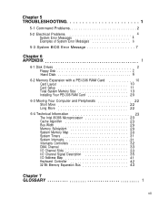
Chapter 5 TROUBLESHOOTING 1 5-1 Command Problems 2 5-2 Electrical Problems 4 System Error Messages 4 Examples of System Error Messages 6 5-3 System BIOS Error Message 7 Chapter 6 APPENDIX 1 6-1 Disk Drives 2 Floppy Disk 2 Hard Disk 6 6-2 Memory Expansion with a PEI-306 RAM Card 10 Card Layout 10 Card Setup 11 Total System Memory Size 13 Installing Your PEI-306 RAM Card 20 6-3 Moving Your Computer and Peripherals 22 Short Move 22 Long Move 22 6-4 Technical Information 23 The Intel 80386 Microprocessor 23 Cache Algorithm 23...
Chapter 5 TROUBLESHOOTING 1 5-1 Command Problems 2 5-2 Electrical Problems 4 System Error Messages 4 Examples of System Error Messages 6 5-3 System BIOS Error Message 7 Chapter 6 APPENDIX 1 6-1 Disk Drives 2 Floppy Disk 2 Hard Disk 6 6-2 Memory Expansion with a PEI-306 RAM Card 10 Card Layout 10 Card Setup 11 Total System Memory Size 13 Installing Your PEI-306 RAM Card 20 6-3 Moving Your Computer and Peripherals 22 Short Move 22 Long Move 22 6-4 Technical Information 23 The Intel 80386 Microprocessor 23 Cache Algorithm 23...

User Manual
Page 9
List of Figures Chapter 1 SYSTEM OVERVIEW Figure 1-1: Quick Start 3 Figure 1-2: System Configuration 6 Figure 1-3: System Unit Case 7 Figure 1-4: Front Panel 8 Figure 1-5: Keylock and Two Security-Lock Keys 9 Figure 1-6: Rear Panel 10 Figure 1-7: Connecting the Keyboard Cable 11 Figure 1-8: System Power Cord 12 Figure 1-9: Two Kinds of Display Connectors 13 Figure 1-10: Voltage Switch 14 Figure 1-11: System Unit Connected to Peripherals 16 Figure 1-12: Installing Floppy and Hard Disk Drives 17 Figure...
List of Figures Chapter 1 SYSTEM OVERVIEW Figure 1-1: Quick Start 3 Figure 1-2: System Configuration 6 Figure 1-3: System Unit Case 7 Figure 1-4: Front Panel 8 Figure 1-5: Keylock and Two Security-Lock Keys 9 Figure 1-6: Rear Panel 10 Figure 1-7: Connecting the Keyboard Cable 11 Figure 1-8: System Power Cord 12 Figure 1-9: Two Kinds of Display Connectors 13 Figure 1-10: Voltage Switch 14 Figure 1-11: System Unit Connected to Peripherals 16 Figure 1-12: Installing Floppy and Hard Disk Drives 17 Figure...

User Manual
Page 10
... Processor 17 Figure 2-14: Location of Coprocessor 18 Figure 2-15: System and Video BIOS 19 Figure 2-16: ROM Installation 21 Figure 2-17: PEM-3300 Motherboard Layout 23 Figure 2-18: DIP-Type Cache RAM 24 Figure 2-19: SIP-Type DRAM 24 Figure 2-20: The Six-Switch DIP SW1 25 Figure 2-21: Location of Jumpers and Connectors of PEM-3300 . . 28 Figure 2-22: An Example of Three-Pin Jumper Setting...
... Processor 17 Figure 2-14: Location of Coprocessor 18 Figure 2-15: System and Video BIOS 19 Figure 2-16: ROM Installation 21 Figure 2-17: PEM-3300 Motherboard Layout 23 Figure 2-18: DIP-Type Cache RAM 24 Figure 2-19: SIP-Type DRAM 24 Figure 2-20: The Six-Switch DIP SW1 25 Figure 2-21: Location of Jumpers and Connectors of PEM-3300 . . 28 Figure 2-22: An Example of Three-Pin Jumper Setting...
User Manual
Page 38
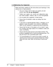
... thoroughfares. It is equipped with a 3-wire grounding-type plug. 1-12 Maintaining Your Equipment Read and follow carefully all the instructions and warnings in this product yourself, as opening and removing covers exposes dangerous voltage areas and other risks. Do not use a damp cloth to experienced service personnel. Only use detergents! Refer all such problems to clean your equipment to repair the system unit, monitor/s, cables/wires.
... thoroughfares. It is equipped with a 3-wire grounding-type plug. 1-12 Maintaining Your Equipment Read and follow carefully all the instructions and warnings in this product yourself, as opening and removing covers exposes dangerous voltage areas and other risks. Do not use a damp cloth to experienced service personnel. Only use detergents! Refer all such problems to clean your equipment to repair the system unit, monitor/s, cables/wires.

User Manual
Page 49
Keyboard Lock-/Power LED J2 - Speaker Connector J5 - installed W2 - speed toggled (software) W7 - Turbo LED J3 - Bank 0 DRAM Type Selection 1-2 short - (1Mbit x 9 SIMM DRAM) 2-3 short - (256Kbit x 9 SIMM DRAM) W3 - Cache Size Selection 1-2 short - 64KB cache memory 2-3 short - 256KB cache memory W6 - Power Supply Connector J7 - W5 - Turbo (hardware) 2-3 short - EPROM Type Selection 1-2 short - 27256 2-3 short - 27512 W8 - Keyboard Connector W1 - Turbo Connector 1-2 short - normal (hardware) open - Coprocessor installation short - Quick Reference of Jumper Settings ...
Keyboard Lock-/Power LED J2 - Speaker Connector J5 - installed W2 - speed toggled (software) W7 - Turbo LED J3 - Bank 0 DRAM Type Selection 1-2 short - (1Mbit x 9 SIMM DRAM) 2-3 short - (256Kbit x 9 SIMM DRAM) W3 - Cache Size Selection 1-2 short - 64KB cache memory 2-3 short - 256KB cache memory W6 - Power Supply Connector J7 - W5 - Turbo (hardware) 2-3 short - EPROM Type Selection 1-2 short - 27256 2-3 short - 27512 W8 - Keyboard Connector W1 - Turbo Connector 1-2 short - normal (hardware) open - Coprocessor installation short - Quick Reference of Jumper Settings ...
User Manual
Page 59
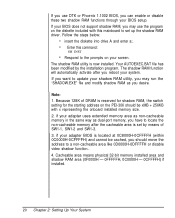
... is set up the shadow RAM driver. Follow the steps below: insert the diskette into drive A and enter a:. The shadow RAM utility is reserved for shadow RAM, the switch setting for the starting address on your adapter uses extended memory area as non-cacheabie memory in the same way as you have to a non-cacheable area like 0D0000H-0DFFFFH or disable video shadow function.. 4. if your BIOS setup. Your...
... is set up the shadow RAM driver. Follow the steps below: insert the diskette into drive A and enter a:. The shadow RAM utility is reserved for shadow RAM, the switch setting for the starting address on your adapter uses extended memory area as non-cacheabie memory in the same way as you have to a non-cacheable area like 0D0000H-0DFFFFH or disable video shadow function.. 4. if your BIOS setup. Your...

User Manual
Page 82
Chapter 2: Setting Up Your System 43 If you have nothing else left to do, close the case according to go. The pinouts for the power supply connectors are as follows: Table 2-13: Power Supply Pinouts Once you have completed connecting the cables the RAM Card is installed and ready to the instructions in your system manual.
Chapter 2: Setting Up Your System 43 If you have nothing else left to do, close the case according to go. The pinouts for the power supply connectors are as follows: Table 2-13: Power Supply Pinouts Once you have completed connecting the cables the RAM Card is installed and ready to the instructions in your system manual.

User Manual
Page 86
... your hard disk If you start DOS. Press the reset button on the monitor. This is off Insert DOS disk 1 into the computer's electronic memory. Turn on the computer and respond to the prompts displayed on your front panel (hardware reset) or hold down the , and keys at the same time (software reset) to your system. System Messages Refer to reboot your MS-DOS User's Guide and Reference manual for Disk Operating...
... your hard disk If you start DOS. Press the reset button on the monitor. This is off Insert DOS disk 1 into the computer's electronic memory. Turn on the computer and respond to the prompts displayed on your front panel (hardware reset) or hold down the , and keys at the same time (software reset) to your system. System Messages Refer to reboot your MS-DOS User's Guide and Reference manual for Disk Operating...
User Manual
Page 87
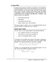
... functions are supported: High density disk drives A password User-defined hard disk type System utilities -timer and calculator The setup program is simple to use the DOS DEBUG command as get information on hard disk types. System Setup Program You will need to run the setup program in the configuration you want for your computer is turned on the motherboard. If the battery for the first time, when adding or removing any other key to...
... functions are supported: High density disk drives A password User-defined hard disk type System utilities -timer and calculator The setup program is simple to use the DOS DEBUG command as get information on hard disk types. System Setup Program You will need to run the setup program in the configuration you want for your computer is turned on the motherboard. If the battery for the first time, when adding or removing any other key to...

User Manual
Page 92
... Operations Following is a brief explanation of all the DOS commands, refer to your computer. Starting MS-DOS If you are using a hard disk with DOS already installed, the computer will see a message similar to the following: Current date is Fri 01-01-1990 Enter new date (MM-DD-YY): For the new date, key in drive "A" and switch on your DOS user manual. Time...
... Operations Following is a brief explanation of all the DOS commands, refer to your computer. Starting MS-DOS If you are using a hard disk with DOS already installed, the computer will see a message similar to the following: Current date is Fri 01-01-1990 Enter new date (MM-DD-YY): For the new date, key in drive "A" and switch on your DOS user manual. Time...
User Manual
Page 112
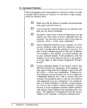
... computer or electronic hardware store. 2 Chapter 5: Troubleshooting Before taking your MS-DOS manual for major surgery, check the following items: Make sure that your hardware? Is it with a certain software program or with the hardware, try to narrow down the message or print it out with software, you have power and are not shared by using the + keys combination. Keyboard? Printer? You...
... computer or electronic hardware store. 2 Chapter 5: Troubleshooting Before taking your MS-DOS manual for major surgery, check the following items: Make sure that your hardware? Is it with a certain software program or with the hardware, try to narrow down the message or print it out with software, you have power and are not shared by using the + keys combination. Keyboard? Printer? You...

User Manual
Page 113
... following instructions will help you are connected well? Chapter 5: Troubleshooting 3 Is the power fuse burned out? Make sure that other problems might stem from system software, applications or other peripherals. Are all the external and internal connectors are running software compatible with your display port, because some common problems. However, you should be aware that you solve some software can only run in the MGA display mode. If you using a startup disk...
... following instructions will help you are connected well? Chapter 5: Troubleshooting 3 Is the power fuse burned out? Make sure that other problems might stem from system software, applications or other peripherals. Are all the external and internal connectors are running software compatible with your display port, because some common problems. However, you should be aware that you solve some software can only run in the MGA display mode. If you using a startup disk...

User Manual
Page 121
... hard disk drives. Be certain to refer to the manuals for both the disk drive and the controller card for any additional specific information regarding them that may be installed in the system unit. Follow the instructions below : Figure 6-1: Fasten the Brackets on Figure 2-35. installation of importance. Screw the metal guides to do so. Floppy Disk To install or remove floppy disk drives, follow the step below: Open...
... hard disk drives. Be certain to refer to the manuals for both the disk drive and the controller card for any additional specific information regarding them that may be installed in the system unit. Follow the instructions below : Figure 6-1: Fasten the Brackets on Figure 2-35. installation of importance. Screw the metal guides to do so. Floppy Disk To install or remove floppy disk drives, follow the step below: Open...

User Manual
Page 129
The '386 RAM Card makes use in a 32-bit expansion slot designed for maximum expandability. Figure 6-10: PEI-306 RAM Card Layout 10 Chapter 6: Appendix Card Layout The figures below will familiarize you with a PEI-306 RAM Card The PEI-306 '386 RAM Card is a flexible memory solution for your system's motherboard. With so many memory configurations, setup becomes a major consideration. The PEI-306 '386 RAM Card can be installed in mind with all configuration settings made on...
The '386 RAM Card makes use in a 32-bit expansion slot designed for maximum expandability. Figure 6-10: PEI-306 RAM Card Layout 10 Chapter 6: Appendix Card Layout The figures below will familiarize you with a PEI-306 RAM Card The PEI-306 '386 RAM Card is a flexible memory solution for your system's motherboard. With so many memory configurations, setup becomes a major consideration. The PEI-306 '386 RAM Card can be installed in mind with all configuration settings made on...

User Manual
Page 141
...moved Turn off all power switches Insert the cardboard diskette/s supplied with the system unit into the disk drive/s and close the disk drive levers Detach all cables and cords. Ensure that you take the following steps before moving any items, follow the instructions stated above. Before moving from one location to...shipping and handling. Next, coil and tie them to protect the connectors Move each item separately Long Move This kind of move involves use of this is backed up your hard disk to another location. Next, repack all items in your computer and its peripheral ...
...moved Turn off all power switches Insert the cardboard diskette/s supplied with the system unit into the disk drive/s and close the disk drive levers Detach all cables and cords. Ensure that you take the following steps before moving any items, follow the instructions stated above. Before moving from one location to...shipping and handling. Next, coil and tie them to protect the connectors Move each item separately Long Move This kind of move involves use of this is backed up your hard disk to another location. Next, repack all items in your computer and its peripheral ...
User Manual
Page 142
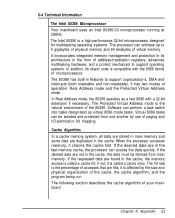
... has two modes of your mainboard. If the requested data are hits; 6-4 Technical Information The Intel 80386 Microprocessor Your mainboard uses an Intel 80386-33 microprocessor running at 33MHz. It incorporates integrated memory management and protection in its architecture in the cache. When the processor accesses memory, it is a high-performance 32-bit microprocessor designed for multitasking operating systems. The processor can...
... has two modes of your mainboard. If the requested data are hits; 6-4 Technical Information The Intel 80386 Microprocessor Your mainboard uses an Intel 80386-33 microprocessor running at 33MHz. It incorporates integrated memory management and protection in its architecture in the cache. When the processor accesses memory, it is a high-performance 32-bit microprocessor designed for multitasking operating systems. The processor can...

User Manual
Page 165
... come across frequently in this is used to the motherboard. A value given to specific memory locations so that devices do not have the same address. ASCII code includes both control and graphic characters, and is used for Information Interchange. Make sure that data can be an address conflict. ASCII - back up (v) - add-on a printed circuit board for RAM chips is an acronym for the...
... come across frequently in this is used to the motherboard. A value given to specific memory locations so that devices do not have the same address. ASCII code includes both control and graphic characters, and is used for Information Interchange. Make sure that data can be an address conflict. ASCII - back up (v) - add-on a printed circuit board for RAM chips is an acronym for the...

User Manual
Page 171
... computer, you 'll need to simulate a hard disk. This section guides you through the preparations you 're advised to be viewed, altered or stored. Although this system has been designed to read this section will help you to ensure the long life and troublefree operation of memory used to make before operating your computer. High-speed virtual disk - window - If this is...
... computer, you 'll need to simulate a hard disk. This section guides you through the preparations you 're advised to be viewed, altered or stored. Although this system has been designed to read this section will help you to ensure the long life and troublefree operation of memory used to make before operating your computer. High-speed virtual disk - window - If this is...


