

User Manual
Page 5
Contents Chapter 1 System Overview 1 1-1 Introduction 2 Operating System 2 1-2 Quick Start 3 1-3 Features 4 1-4 Specifications 5 1-5 Example of a System Configuration 6 l-6 System Unit 7 1-7 Control Panel 8 Reset Button 8 Turbo Button 8 Indicator Lights 8 Keyboard Lock 9 System Power Switch 9 1-8 Rear Panel 10 Keyboard Connector 11 Power Cord Connector 12 Display Port 13 Power Voltage Setting 14 Power Cord Specification 14 1-9 Other Peripherals 15 1-10 Disk Drives 16 Floppy Disks 17 Hard Disks 19 1-11 Keyboard 20 1-12 Maintaining Your Equipment 21 IV
Contents Chapter 1 System Overview 1 1-1 Introduction 2 Operating System 2 1-2 Quick Start 3 1-3 Features 4 1-4 Specifications 5 1-5 Example of a System Configuration 6 l-6 System Unit 7 1-7 Control Panel 8 Reset Button 8 Turbo Button 8 Indicator Lights 8 Keyboard Lock 9 System Power Switch 9 1-8 Rear Panel 10 Keyboard Connector 11 Power Cord Connector 12 Display Port 13 Power Voltage Setting 14 Power Cord Specification 14 1-9 Other Peripherals 15 1-10 Disk Drives 16 Floppy Disks 17 Hard Disks 19 1-11 Keyboard 20 1-12 Maintaining Your Equipment 21 IV

User Manual
Page 6
... 1 2-1 PEM-2530 Motherboard 2 80386 CPU 3 Math Coprocessor 4 Expansion Bus 6 RAM Subsystem 7 ROM Installation 7 Jumper Settings for Connectors 8 Shadow RAM 11 Onboard System Memory Size 13 1MB Total Onboard Memory 16 2MB Total Onboard Memory 17 4MB Total Onboard Memory 18 8MB Total Onboard Memory 19 32-bit Local Memory Size 20 Starting Address 21 Factory Default Settings 22 2-2 Installation 23 Connection to Power Supply 24 Choosing a Power Supply 25 2-3 Entering 25MHz Turbo Mode 26 Software Turbo Switch 26 Hardware Turbo Switch 26 V
... 1 2-1 PEM-2530 Motherboard 2 80386 CPU 3 Math Coprocessor 4 Expansion Bus 6 RAM Subsystem 7 ROM Installation 7 Jumper Settings for Connectors 8 Shadow RAM 11 Onboard System Memory Size 13 1MB Total Onboard Memory 16 2MB Total Onboard Memory 17 4MB Total Onboard Memory 18 8MB Total Onboard Memory 19 32-bit Local Memory Size 20 Starting Address 21 Factory Default Settings 22 2-2 Installation 23 Connection to Power Supply 24 Choosing a Power Supply 25 2-3 Entering 25MHz Turbo Mode 26 Software Turbo Switch 26 Hardware Turbo Switch 26 V

User Manual
Page 9
...1 6-l Installing Disk Drives 2 Installing 5.25 Disk Drives 2 Installing 3.5" Disk Drives 4 Connecting Cables to Disk Drives 5 Connecting Cables to Floppy Disk Drives 6 Connecting Cables to Hard disks 7 Removal 8 6-2 Quick Reference for Jumper Settings 9 6-3 Expanding Your Memory with a PEI-306 RAM Card 11 Card Layout 11 Card Setup 12 Total System Memory Size 14 Installing Your PEI-306 RAM Card 17 6-4 Moving Your Computer and Peripherals 19 ShortMove 19 Long Move 19 6-5 Technical Information 20 Overview 20 System Timers 21 System Interrupts 22 ROM Subsystem 23 RAM Subsystem...
...1 6-l Installing Disk Drives 2 Installing 5.25 Disk Drives 2 Installing 3.5" Disk Drives 4 Connecting Cables to Disk Drives 5 Connecting Cables to Floppy Disk Drives 6 Connecting Cables to Hard disks 7 Removal 8 6-2 Quick Reference for Jumper Settings 9 6-3 Expanding Your Memory with a PEI-306 RAM Card 11 Card Layout 11 Card Setup 12 Total System Memory Size 14 Installing Your PEI-306 RAM Card 17 6-4 Moving Your Computer and Peripherals 19 ShortMove 19 Long Move 19 6-5 Technical Information 20 Overview 20 System Timers 21 System Interrupts 22 ROM Subsystem 23 RAM Subsystem...

User Manual
Page 11
... Three-Pin Jumper Setting 1 3 Figure 2-12: Dip Switch SW1 14 Figure 2-13: 1MB Total Onboard Memory 16 Figure 2-14: 2MB Total Onboard Memory 17 Figure 2-15: 4MB Total Onboard Memory 18 Figure 2-16: 8MB Total Onboard Memory 19 Figure 2-17: Support Posts Tying Up Two RAM Modules 19 Figure 2-18: Unpacking Your Main System 23 Figure 2-19: Connecting to a Power Supply 24 Chapter 3 Operating...
... Three-Pin Jumper Setting 1 3 Figure 2-12: Dip Switch SW1 14 Figure 2-13: 1MB Total Onboard Memory 16 Figure 2-14: 2MB Total Onboard Memory 17 Figure 2-15: 4MB Total Onboard Memory 18 Figure 2-16: 8MB Total Onboard Memory 19 Figure 2-17: Support Posts Tying Up Two RAM Modules 19 Figure 2-18: Unpacking Your Main System 23 Figure 2-19: Connecting to a Power Supply 24 Chapter 3 Operating...

User Manual
Page 12
... Drives 4 Figure 6-4: Installing 3.5 Disk Drives 4 Figure 6-5: Cables for Disk Drives 5 Figure 6-6: Connecting to a Floppy Disk Drive 6 Figure 6-7: Connecting Cables to Floppy Disk Drives 6 Figure 6-8: Connecting to a Hard Disk Drive 7 Figure 6-9: Connecting the Controller Cable 7 Figure 6-10: Connecting the Data Cable 7 Figure 6-11: Connecting Cables to Hard Disk Drives 8 Figure 6-12: PEI-306 RAM Card Layout 11 Figure 6-13: SIMM-Type RAM Module 12 Figure 6-14: 32-Bit Expansion Slot for PEI-306 RAM Card 17 Figure 6-15: Installing a PEI-306 RAM Card 18 Figure 6-16: Sixty-Two Pin...
... Drives 4 Figure 6-4: Installing 3.5 Disk Drives 4 Figure 6-5: Cables for Disk Drives 5 Figure 6-6: Connecting to a Floppy Disk Drive 6 Figure 6-7: Connecting Cables to Floppy Disk Drives 6 Figure 6-8: Connecting to a Hard Disk Drive 7 Figure 6-9: Connecting the Controller Cable 7 Figure 6-10: Connecting the Data Cable 7 Figure 6-11: Connecting Cables to Hard Disk Drives 8 Figure 6-12: PEI-306 RAM Card Layout 11 Figure 6-13: SIMM-Type RAM Module 12 Figure 6-14: 32-Bit Expansion Slot for PEI-306 RAM Card 17 Figure 6-15: Installing a PEI-306 RAM Card 18 Figure 6-16: Sixty-Two Pin...

User Manual
Page 14
... Speaker 21 Table 6-12: Interrupt Controllers 22 Table 6-13: DMA Channels 24 Table 6-14: Addresses for the Page Register 25 Table 6-15: Address Generation for DMA Channels 3 Through 0 . . . .25 Table 6-16: Address Generation for DMA Channels 7 Through 5 2 5 XIII Chapter 6 Appendix 1 Table 6-1: Jumper W1 and Switch SW1 Settings 9 Table 6-2: Jumper W2 9 Table 6-3: Jumper W3 9 Table 6-4: Jumper W4 10 Table 6-5: Jumpers W1 W3 Settings...
... Speaker 21 Table 6-12: Interrupt Controllers 22 Table 6-13: DMA Channels 24 Table 6-14: Addresses for the Page Register 25 Table 6-15: Address Generation for DMA Channels 3 Through 0 . . . .25 Table 6-16: Address Generation for DMA Channels 7 Through 5 2 5 XIII Chapter 6 Appendix 1 Table 6-1: Jumper W1 and Switch SW1 Settings 9 Table 6-2: Jumper W2 9 Table 6-3: Jumper W3 9 Table 6-4: Jumper W4 10 Table 6-5: Jumpers W1 W3 Settings...
User Manual
Page 38
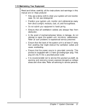
... 7: System Overview 21 Do not submit your system unit and monitor case. This plug will only fit into a grounded power outlet. Do not use a damp cloth to clean your equipment to repair the system unit, monitor/s, cables/wires. Refer all the instructions and warnings in this product yourself, as opening and removing covers exposes dangerous voltage areas and other risks. Ensure that might obstruct...
... 7: System Overview 21 Do not submit your system unit and monitor case. This plug will only fit into a grounded power outlet. Do not use a damp cloth to clean your equipment to repair the system unit, monitor/s, cables/wires. Refer all the instructions and warnings in this product yourself, as opening and removing covers exposes dangerous voltage areas and other risks. Ensure that might obstruct...

User Manual
Page 49
Refer to the figure for the pinouts of jumper J3. Refer to the figure below for the settings. Table 2-6: Jumper W6 10 Chapter 2: Setting Up your System Jumper J3 Pinouts Figure 2-8: Jumper J3 Pinouts Video Selection (Jumper W6) Jumper W6 is used to connect a speaker. Speaker Connector (Jumper J3) Jumper J3 is used to select display mode. When the four pins are in a closed circuit, the speaker is functional.
Refer to the figure for the pinouts of jumper J3. Refer to the figure below for the settings. Table 2-6: Jumper W6 10 Chapter 2: Setting Up your System Jumper J3 Pinouts Figure 2-8: Jumper J3 Pinouts Video Selection (Jumper W6) Jumper W6 is used to connect a speaker. Speaker Connector (Jumper J3) Jumper J3 is used to select display mode. When the four pins are in a closed circuit, the speaker is functional.

User Manual
Page 51
... on your screen according to update your BIOS setup. To install shadow RAM program, follow the setps below: • Insert the diskette into drive A and enter a:. • Enter this mainboard to the system setup manual for more information. The shadow RAM function will automatic active after you can enable or disable these two shadow RAM functions through your shadow RAM function. Refer to set up the shadow RAM driver.
... on your screen according to update your BIOS setup. To install shadow RAM program, follow the setps below: • Insert the diskette into drive A and enter a:. • Enter this mainboard to the system setup manual for more information. The shadow RAM function will automatic active after you can enable or disable these two shadow RAM functions through your shadow RAM function. Refer to set up the shadow RAM driver.

User Manual
Page 64
... to the instructions in your system. But, if you may need to purchase a power supply in a later time, the following is recommended for choosing a suitable power supply • The power-good signal should have completed connecting the cables and installing the RAM Cards, close the case according to indicate proper operation of interest. Choosing a Power Supply A 200W power supply is installed in your system manual. Otherwise, the data setting in order...
... to the instructions in your system. But, if you may need to purchase a power supply in a later time, the following is recommended for choosing a suitable power supply • The power-good signal should have completed connecting the cables and installing the RAM Cards, close the case according to indicate proper operation of interest. Choosing a Power Supply A 200W power supply is installed in your system manual. Otherwise, the data setting in order...

User Manual
Page 65
... LED will be the Turbo LED. 2-3 Entering 25MHz Turbo Mode The PEM-2530 supports both a software and hardware switch to toggle between Turbo and Normal speeds from the keyboard. The two switches are mutually exclusive. To switch the speed to enter 25MHz mode. When you turn the system on the Turbo LED, refer to pins one and two of operation mode will light. For more information on will turn into a box. Hardware Turbo Switch...
... LED will be the Turbo LED. 2-3 Entering 25MHz Turbo Mode The PEM-2530 supports both a software and hardware switch to toggle between Turbo and Normal speeds from the keyboard. The two switches are mutually exclusive. To switch the speed to enter 25MHz mode. When you turn the system on the Turbo LED, refer to pins one and two of operation mode will light. For more information on will turn into a box. Hardware Turbo Switch...

User Manual
Page 68
... the screen following the RAM test: Non-system disk or disk error Replace and strike any key when ready Then, you to start your front panel (hardware reset) or hold down the DOS makes it easy for Disk Operating System. Starting DOS when the computer is off: • Insert DOS disk 1 into disk drive A and close the drive lever. You should : l Insert DOS disk 1 into the computer's electronic memory. This is a set of...
... the screen following the RAM test: Non-system disk or disk error Replace and strike any key when ready Then, you to start your front panel (hardware reset) or hold down the DOS makes it easy for Disk Operating System. Starting DOS when the computer is off: • Insert DOS disk 1 into disk drive A and close the drive lever. You should : l Insert DOS disk 1 into the computer's electronic memory. This is a set of...

User Manual
Page 69
... your computer. Starting MS-DOS If you are using a hard disk with DOS already installed, the computer will see a message similar to the following: Current date is Fri 01-01-1990 Enter new date (MM-DD-YY): For the new date, key in drive "A" and switch on your DOS user manual. 3-2 DOS Operations Following is now booted and ready to run application programs. Chapter 3: Operating Your System...
... your computer. Starting MS-DOS If you are using a hard disk with DOS already installed, the computer will see a message similar to the following: Current date is Fri 01-01-1990 Enter new date (MM-DD-YY): For the new date, key in drive "A" and switch on your DOS user manual. 3-2 DOS Operations Following is now booted and ready to run application programs. Chapter 3: Operating Your System...
User Manual
Page 77
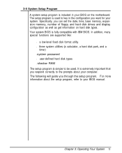
... are supported like: l a low-level fixed disk format utility l three system utilities (a calculator, a hard disk park, and a timer) l system password l user-defined hard disk types l shadow RAM The setup program is fully compatible with IBM BIOS. Chapter 3: Operating Your System 11 Your system BIOS is simple to be used to your BIOS manual. It is extremely important that you can set the date, time, base memory, expansion memory, number of floppy and hard disk drives and display configuration...
... are supported like: l a low-level fixed disk format utility l three system utilities (a calculator, a hard disk park, and a timer) l system password l user-defined hard disk types l shadow RAM The setup program is fully compatible with IBM BIOS. Chapter 3: Operating Your System 11 Your system BIOS is simple to be used to your BIOS manual. It is extremely important that you can set the date, time, base memory, expansion memory, number of floppy and hard disk drives and display configuration...

User Manual
Page 98
... you are connected well? Make sure that other problems might stem from system software, applications or other peripherals. Are you solve some software programs can only run on the MGA display mode. Is your disk formatted? Are all the external and internal connectors are running software compatible with your system still does not function properly, check the following instructions will help you using a startup disk? Chapter 5: Troubleshooting 3 The following...
... you are connected well? Make sure that other problems might stem from system software, applications or other peripherals. Are you solve some software programs can only run on the MGA display mode. Is your disk formatted? Are all the external and internal connectors are running software compatible with your system still does not function properly, check the following instructions will help you using a startup disk? Chapter 5: Troubleshooting 3 The following...

User Manual
Page 107
Installing 3.5" Disk Drives The installation of a 3.5" disk drive is similar to that of a 5.25" disk drive. • First, fasten the bracket to the figure below: Figure 6-4: Installing 3.5 Disk Drives 4 Chapter 6: Appendix Refer to the drives. Figure 6-3: Fastening the bracket to 3.5 Disk Drives • Next, place the disk drive inside the bay and fasten the brackets to the chassis.
Installing 3.5" Disk Drives The installation of a 3.5" disk drive is similar to that of a 5.25" disk drive. • First, fasten the bracket to the figure below: Figure 6-4: Installing 3.5 Disk Drives 4 Chapter 6: Appendix Refer to the drives. Figure 6-3: Fastening the bracket to 3.5 Disk Drives • Next, place the disk drive inside the bay and fasten the brackets to the chassis.

User Manual
Page 114
... the '386 RAM Card, the jumpers, the DIP switch as well as banks 0, 1, and 2. he figures below will familiarize you with all configuration settings made on one DIP switch and a few jumpers. Card Layout he PEI-306 RAM Card makes use in a 32-bit expansion slot designed for your system's motherboard. It can be installed in mind with the layout of memory for maximum expandability. The PEI-306 RAM Card has been...
... the '386 RAM Card, the jumpers, the DIP switch as well as banks 0, 1, and 2. he figures below will familiarize you with all configuration settings made on one DIP switch and a few jumpers. Card Layout he PEI-306 RAM Card makes use in a 32-bit expansion slot designed for your system's motherboard. It can be installed in mind with the layout of memory for maximum expandability. The PEI-306 RAM Card has been...

User Manual
Page 122
...your hard disk is being moved. • Turn off all power switches. • Insert the cardboard diskette/s supplied with the system unit into the disk drive/s and close the disk drive levers. • Detach all items in their original packing cases. Long Move This kind of move involves use ...instructions stated above. 6-4 Moving Your Computer and Peripherals Your personal computer and its peripherals from one location to another in the same building. This command will lock up onto flop py disks. • Enter the DOS system program and invoke the PARK command. Next, repack all cables...
...your hard disk is being moved. • Turn off all power switches. • Insert the cardboard diskette/s supplied with the system unit into the disk drive/s and close the disk drive levers. • Detach all items in their original packing cases. Long Move This kind of move involves use ...instructions stated above. 6-4 Moving Your Computer and Peripherals Your personal computer and its peripherals from one location to another in the same building. This command will lock up onto flop py disks. • Enter the DOS system program and invoke the PARK command. Next, repack all cables...

User Manual
Page 135
... on card - The ASCII code includes both control and graphic characters, and is given to specific memory locations so that devices do not have the same address. To make a spare copy of a disk or of a disk or file. backup (n) - Otherwise, there will come across frequently in this is usually divided into rows. A type of your computer. bank - Chapter 7: Glossary 1 add-on a printed circuit board...
... on card - The ASCII code includes both control and graphic characters, and is given to specific memory locations so that devices do not have the same address. To make a spare copy of a disk or of a disk or file. backup (n) - Otherwise, there will come across frequently in this is usually divided into rows. A type of your computer. bank - Chapter 7: Glossary 1 add-on a printed circuit board...
User Manual
Page 141
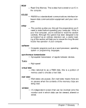
... - If this is your first computer, you 'll need to as a RAM disk, this section carefully. Also referred to make before operating your computer. RS232 is a portion of signals between devices. Although this section will help you to simulate a hard disk. software - Syncopated transmission of memory used to ensure the long life and trouble free operation of your computer. wait state - Zero wait state...
... - If this is your first computer, you 'll need to as a RAM disk, this section carefully. Also referred to make before operating your computer. RS232 is a portion of signals between devices. Although this section will help you to simulate a hard disk. software - Syncopated transmission of memory used to ensure the long life and trouble free operation of your computer. wait state - Zero wait state...


