

Product Information Guide
Page 1
...backup battery option slots AC inlet - internal and external cache controllable through SETUP Math coprocessor Math coprocessor built into the 586-class processor Clock/ calendar Real-time clock, calendar, and CMOS RAM socketed on main system board with access speed of system and video BIOS ROM into RAM; SPEED light POWER light hard disk access light (HDD) RESET drive bays button I diskette drive POWER button POWER light SPEED light access light (HDD) drive bays printer (parallel EPSON ActionPC 8000, ActionTower 8000 Computer Specifications CPU and Memory 64-bit CPU 586...
...backup battery option slots AC inlet - internal and external cache controllable through SETUP Math coprocessor Math coprocessor built into the 586-class processor Clock/ calendar Real-time clock, calendar, and CMOS RAM socketed on main system board with access speed of system and video BIOS ROM into RAM; SPEED light POWER light hard disk access light (HDD) RESET drive bays button I diskette drive POWER button POWER light SPEED light access light (HDD) drive bays printer (parallel EPSON ActionPC 8000, ActionTower 8000 Computer Specifications CPU and Memory 64-bit CPU 586...

Product Information Guide
Page 2
... main system board; 6-pin mini DIN connector Option slots Connector card with 2MB of four drives Other devices Half-height tape drives, CD-ROM drives, optical drives, PCMCIA card readers, or other IDE devices" below); maximum of video RAM; four-key cursor control keypad; 12 function keys Mouse Detachable, two-button, PS/2 compatible SETUP Program Stored in the 640 x 480 resolution with 2MB of video Diskette Hard disk and other IDE devices Interfaces Monitor Parallel Serial Keyboard Mouse Controller on main system board support up to...
... main system board; 6-pin mini DIN connector Option slots Connector card with 2MB of four drives Other devices Half-height tape drives, CD-ROM drives, optical drives, PCMCIA card readers, or other IDE devices" below); maximum of video RAM; four-key cursor control keypad; 12 function keys Mouse Detachable, two-button, PS/2 compatible SETUP Program Stored in the 640 x 480 resolution with 2MB of video Diskette Hard disk and other IDE devices Interfaces Monitor Parallel Serial Keyboard Mouse Controller on main system board support up to...

Product Information Guide
Page 9
... the system board battery. 5. Also, remove the hard disk drive ribbon connector from a system diskette in IDE hard disk drive interface. If the auto-sensing feature does not produce a match for the drive. Password If you forget your password, you can define your CMOS memory as the type and entering the drive's parameters. Run SETUP to 2-3. EPSON ActionPC 8000, ActionTower 8000 Installation/Support Tips Installing Diskette Drives 0 Make sure that you must discharge your own drive type by setting jumper JP2 to enter a new password, if...
... the system board battery. 5. Also, remove the hard disk drive ribbon connector from a system diskette in IDE hard disk drive interface. If the auto-sensing feature does not produce a match for the drive. Password If you forget your password, you can define your CMOS memory as the type and entering the drive's parameters. Run SETUP to 2-3. EPSON ActionPC 8000, ActionTower 8000 Installation/Support Tips Installing Diskette Drives 0 Make sure that you must discharge your own drive type by setting jumper JP2 to enter a new password, if...

Product Information Guide
Page 10
EPSON ActionPC 8000, ActionTower 8000 Information Reference List Engineering Change Notices Technical Information Bulletins None. Product Support Bulletins None. ActionPC 8000, ActionTower 8000 9/95 Related Documentation TM-ACTPCT80 EPSON ActionPC 8000, ActionTower 8000 Service Manual PL-ACTPCT80 EPSON ActionPC 8000, ActionTower 8000 Parts Price List 400434500-1 EPSON ActionPC 8000, ActionTower 8000 User's Guide 10 -
EPSON ActionPC 8000, ActionTower 8000 Information Reference List Engineering Change Notices Technical Information Bulletins None. Product Support Bulletins None. ActionPC 8000, ActionTower 8000 9/95 Related Documentation TM-ACTPCT80 EPSON ActionPC 8000, ActionTower 8000 Service Manual PL-ACTPCT80 EPSON ActionPC 8000, ActionTower 8000 Parts Price List 400434500-1 EPSON ActionPC 8000, ActionTower 8000 User's Guide 10 -

User Manual
Page 10
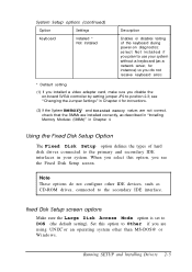
... Use This Manual This manual contains the information you need to support PCI option cards. PCI Auto-configuration The PCI auto-configuration utility works with the SETUP program to get the best results from a diskette, hard disk, or network server. You don't have to find the sections you need . You can also customize these resources in a flash ROM device, you use frequently. You can upgrade the BIOS by running a utility from your system and connecting peripheral devices such as the monitor...
... Use This Manual This manual contains the information you need to support PCI option cards. PCI Auto-configuration The PCI auto-configuration utility works with the SETUP program to get the best results from a diskette, hard disk, or network server. You don't have to find the sections you need . You can also customize these resources in a flash ROM device, you use frequently. You can upgrade the BIOS by running a utility from your system and connecting peripheral devices such as the monitor...

User Manual
Page 11
... slimline computer. Where to install and remove mass storage devices on the tower computer. Chapter 6 explains how to remove and replace the computer's cover, change jumper settings, and install optional equipment such as resetting the computer and using passwords. Chapter 7 contains troubleshooting tips. EPSON also provides the following services when you purchased your computer, including DMA and IRQ assignments. Chapter 3 covers general operating procedures, such as option cards, memory modules, and video memory. Introduction 5
... slimline computer. Where to install and remove mass storage devices on the tower computer. Chapter 6 explains how to remove and replace the computer's cover, change jumper settings, and install optional equipment such as resetting the computer and using passwords. Chapter 7 contains troubleshooting tips. EPSON also provides the following services when you purchased your computer, including DMA and IRQ assignments. Chapter 3 covers general operating procedures, such as option cards, memory modules, and video memory. Introduction 5

User Manual
Page 30
...-only memory) chip on the system board. You only need to change. Running SETUP and lnstalling Drivers 2-1 Any configuration information you set is backed up by a battery, so it is not erased when you 're using an operating system other than Windows. You may also want to install drivers and utilities for your hardware configuration, security options, and power-saving features that SETUP allows you to install these drivers if you turn off or reset...
...-only memory) chip on the system board. You only need to change. Running SETUP and lnstalling Drivers 2-1 Any configuration information you set is backed up by a battery, so it is not erased when you 're using an operating system other than Windows. You may also want to install drivers and utilities for your hardware configuration, security options, and power-saving features that SETUP allows you to install these drivers if you turn off or reset...
User Manual
Page 34
... keyboard errors * Default setting (1) If you installed a video adapter card, make sure you disable the on-board SVGA controller by setting jumper JP2 to the primary and secondary IDE interfaces in Chapter 4 for instance) so you select this option to the secondary IDE interface. Running SETUP and lnstalling Drivers 2-5 When you do not configure other than MS-DOS@ or Windows. Set this option, you see "Changing the Jumper Settings" in your system without a keyboard (as a network server, for instructions...
... keyboard errors * Default setting (1) If you installed a video adapter card, make sure you disable the on-board SVGA controller by setting jumper JP2 to the primary and secondary IDE interfaces in Chapter 4 for instance) so you select this option to the secondary IDE interface. Running SETUP and lnstalling Drivers 2-5 When you do not configure other than MS-DOS@ or Windows. Set this option, you see "Changing the Jumper Settings" in your system without a keyboard (as a network server, for instructions...

User Manual
Page 35
... drives connected to your own drive parameters (see the next section for that the hard disk uses in multiple sector transfers. The Multi-Sector Transfer option sets the number of sectors per block, the faster your hard drive performs. If this screen, you can select 2, 4, 8, or 16 sectors. 2-6 Running SETUP and Installing Drivers If the drive parameters displayed on the screen do not match your drive, you need to set the remaining options...
... drives connected to your own drive parameters (see the next section for that the hard disk uses in multiple sector transfers. The Multi-Sector Transfer option sets the number of sectors per block, the faster your hard drive performs. If this screen, you can select 2, 4, 8, or 16 sectors. 2-6 Running SETUP and Installing Drivers If the drive parameters displayed on the screen do not match your drive, you need to set the remaining options...
User Manual
Page 41
... configure the devices connected to be set only if you installed older PCI devices that appears when you turn it on or reset it. 2-12 Running SETUP and Installing Drivers These options need to the PCI option slots in slots 1 and 2. Setting the Boot Options When you select Boot Options from the Main Menu, you see the Boot Options screen, which allows you start SETUP. The Slot #l and Slot #2 options allow you to specify whether the device is Enabled. If you disable the message, you turn on diagnostic tests...
... configure the devices connected to be set only if you installed older PCI devices that appears when you turn it on or reset it. 2-12 Running SETUP and Installing Drivers These options need to the PCI option slots in slots 1 and 2. Setting the Boot Options When you select Boot Options from the Main Menu, you see the Boot Options screen, which allows you start SETUP. The Slot #l and Slot #2 options allow you to specify whether the device is Enabled. If you disable the message, you turn on diagnostic tests...
User Manual
Page 49
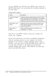
... load ROM values to boot the system and start over Loads the current values stored in the table below. To leave SETUP, press ESC from CMOS Save Values to CMOS Description Loads the factory default settings stored in ROM back into CMOS: if you change your configuration using SETUP and then have problems, you can perform the following functions in CMOS for hard disk drives and other IDE devices. 2-20 Running SETUP and Installing Drivers
... load ROM values to boot the system and start over Loads the current values stored in the table below. To leave SETUP, press ESC from CMOS Save Values to CMOS Description Loads the factory default settings stored in ROM back into CMOS: if you change your configuration using SETUP and then have problems, you can perform the following functions in CMOS for hard disk drives and other IDE devices. 2-20 Running SETUP and Installing Drivers

User Manual
Page 73
...* Off Off On Installing and Removing Options 4-9 Note Any jumpers not listed in the following tables are for 100 MHz CPU) JP16 pins 1-2 Off Off On JP16 pins 3-4 Off On On * Default setting depends on the system board are preset to factory default positions, indicated by an asterisk (*) in the tables below. (See the illustration under "Locating the System Board Components" to locate jumpers.) Use the information in...
...* Off Off On Installing and Removing Options 4-9 Note Any jumpers not listed in the following tables are for 100 MHz CPU) JP16 pins 1-2 Off Off On JP16 pins 3-4 Off On On * Default setting depends on the system board are preset to factory default positions, indicated by an asterisk (*) in the tables below. (See the illustration under "Locating the System Board Components" to locate jumpers.) Use the information in...

User Manual
Page 74
... Jumper setting 1-2 * 2-3 On Off * 1-2 * 2-3 JP13 JP14 Off * On 1-2, 3-4 2-3 * Function Enable VGA controller Disable VGA controller Clears the CMOS SETUP values Normal CMOS operation Disable DRAM parity checking if you installed 32-bit SlMMs Enable DRAM parity checking if you may need to remove them to locate the jumper(s). 2. and single-sided SlMMs Single-sided SlMMs only * Default setting Setting the Jumpers To change a jumper setting, follow these steps: 1. Refer to the illustration under "Locating the System Board Components" to access...
... Jumper setting 1-2 * 2-3 On Off * 1-2 * 2-3 JP13 JP14 Off * On 1-2, 3-4 2-3 * Function Enable VGA controller Disable VGA controller Clears the CMOS SETUP values Normal CMOS operation Disable DRAM parity checking if you installed 32-bit SlMMs Enable DRAM parity checking if you may need to remove them to locate the jumper(s). 2. and single-sided SlMMs Single-sided SlMMs only * Default setting Setting the Jumpers To change a jumper setting, follow these steps: 1. Refer to the illustration under "Locating the System Board Components" to access...
User Manual
Page 107
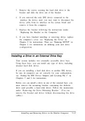
... Device Jumpers and Locating Pin 1" in Chapter 2 for instructions. Using these bays, you have finished installing or removing drives, replace the computer's cover; Remove the screws securing the hard disk drive to disconnect the device cable from its jumper(s) are set correctly for instructions. Replace the bracket following the instructions under "Removing the Drive Mounting Bracket." (You can install a drive in the Slimline Computer 5-13 Installing a Drive in the Computer." 6. see "Running SETUP" in Chapters 5 and 6 for instructions on the system board...
... Device Jumpers and Locating Pin 1" in Chapter 2 for instructions. Using these bays, you have finished installing or removing drives, replace the computer's cover; Remove the screws securing the hard disk drive to disconnect the device cable from its jumper(s) are set correctly for instructions. Replace the bracket following the instructions under "Removing the Drive Mounting Bracket." (You can install a drive in the Slimline Computer 5-13 Installing a Drive in the Computer." 6. see "Running SETUP" in Chapters 5 and 6 for instructions on the system board...
User Manual
Page 144
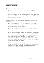
... the card type. In addition, check that its power light is on the keyboard, see if the monitor displays an image. When you installed a display adapter card, make sure the monitor is securely connected to the computer. Also, check the brightness and contrast controls. If you press a mouse button or a key on . Check that the monitor's power switch is on and that you have. see "Changing the Jumper Settings" in Chapter 4 for the Video System option in SETUP; Monitor Problems...
... the card type. In addition, check that its power light is on the keyboard, see if the monitor displays an image. When you installed a display adapter card, make sure the monitor is securely connected to the computer. Also, check the brightness and contrast controls. If you press a mouse button or a key on . Check that the monitor's power switch is on and that you have. see "Changing the Jumper Settings" in Chapter 4 for the Video System option in SETUP; Monitor Problems...
User Manual
Page 153
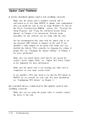
... Jumper Settings" in Chapter 2 for any software you are using the proper cable to securely connect the device to update your configuration after you installed a PCI card, check to set correctly for more information. An external device connected to the option card is not working correctly. If you are using Windows 95, turn on the card. If you install the card. See "Starting the Setup Program" and "Using the Advanced System Setup 0ptions" in Chapter 4 for your main system board...
... Jumper Settings" in Chapter 2 for any software you are using the proper cable to securely connect the device to update your configuration after you installed a PCI card, check to set correctly for more information. An external device connected to the option card is not working correctly. If you are using Windows 95, turn on the card. If you install the card. See "Starting the Setup Program" and "Using the Advanced System Setup 0ptions" in Chapter 4 for your main system board...
User Manual
Page 180
... of computer, A-7 Diagnostics, power-on, 1-11, 2-13, 7-3, 7-17 DIP chips, see Video memory Disk optimization utility, 7-12 Diskette drive accessing, 2-15, 3-11, 7-9, A-6 bays, 1-10,4-6-7,5-2,5-13, 5-15-18, 5-20-21 boot sequence, 2-13, 7-3 cable, 5-4, 5-11-12, 5-14, 5-17, 5-20, 6-11 combo, A-4 configuring, 7-10 connectors, 4-8, 5-4, 5-11, 5-18 controller, A-4 errors, 7-9-10 installing, slimline computer, 5-1-22 installing, tower computer, 6-1-22 interface, 4-8 light, 3-9 power supply cable, 6-12 problems, 7-10 removing, 5-4-5, 5-20-21 restricting access, 2-15, 3-11, 7-9, A-6 types, A-6 2 Index
... of computer, A-7 Diagnostics, power-on, 1-11, 2-13, 7-3, 7-17 DIP chips, see Video memory Disk optimization utility, 7-12 Diskette drive accessing, 2-15, 3-11, 7-9, A-6 bays, 1-10,4-6-7,5-2,5-13, 5-15-18, 5-20-21 boot sequence, 2-13, 7-3 cable, 5-4, 5-11-12, 5-14, 5-17, 5-20, 6-11 combo, A-4 configuring, 7-10 connectors, 4-8, 5-4, 5-11, 5-18 controller, A-4 errors, 7-9-10 installing, slimline computer, 5-1-22 installing, tower computer, 6-1-22 interface, 4-8 light, 3-9 power supply cable, 6-12 problems, 7-10 removing, 5-4-5, 5-20-21 restricting access, 2-15, 3-11, 7-9, A-6 types, A-6 2 Index

User Manual
Page 181
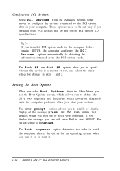
..., A-8 Environments, tested operating, A-15 EPSON, contacting, Intro-6 Ergonomic tips, 3-1-5 Errors controller, 7-18 diskette drive, 7-9-10 hard disk drive, 7-1 1-12 keyboard, 7-6 mouse, 7-6 power-on diagnostics, 1-11 read/ write, 7-12 Expansion buses ISA, Intro-3 PCI, Intro-3 External cache, Intro-2, see also Cache memory F Faceplate removing, 5-15, 6-10 replacing, 5-21 Files AUTOEXEC.BAT, 7-3 CONFIG.SYS, 2-22, 7-3 readme, 2-23 repairing, 7-10 SYSTEM.INI, 2-22 Fixed Disk Setup option, 2-5, 2-7 32 Bit I/ O, 2-7 Autotype Fixed Disk, 2-6 Large Disk Access Mode, 2-5 LBA Mode Control, 2-7 Multi...
..., A-8 Environments, tested operating, A-15 EPSON, contacting, Intro-6 Ergonomic tips, 3-1-5 Errors controller, 7-18 diskette drive, 7-9-10 hard disk drive, 7-1 1-12 keyboard, 7-6 mouse, 7-6 power-on diagnostics, 1-11 read/ write, 7-12 Expansion buses ISA, Intro-3 PCI, Intro-3 External cache, Intro-2, see also Cache memory F Faceplate removing, 5-15, 6-10 replacing, 5-21 Files AUTOEXEC.BAT, 7-3 CONFIG.SYS, 2-22, 7-3 readme, 2-23 repairing, 7-10 SYSTEM.INI, 2-22 Fixed Disk Setup option, 2-5, 2-7 32 Bit I/ O, 2-7 Autotype Fixed Disk, 2-6 Large Disk Access Mode, 2-5 LBA Mode Control, 2-7 Multi...

User Manual
Page 183
... B port, 1-4, see also Keyboard Keyboard connecting, 1-3-5 errors, 7-6 port, 1-3-4, 4-8, A-5 problems, 7-6 specifications, A-6 using, 3-4 Keypad, numeric, 7-6 Keys, SETUP function, 2-3 L Lighting workspace, 3-3-4 Lights, see Indicator lights Location, choosing, 1-1-2 Lockup problems, 7-5 LPT Extended Mode, 1-7 M Main menu, SETUP, 2-2 Mass storage, Intro-2, 5-2, 6-2, A-5-6 Master hard disk drive, 2-7, 5-2, 5-13, 6-3, A-11 Math coprocessor, A-3 Measurements, computer, A-7 Memory addresses, Intro-3 banks, 4-8, 4-12 BIOS ROM, 2-1 cache, see Cache memory clearing, 3-10 CMOS RAM, A-3 configurations...
... B port, 1-4, see also Keyboard Keyboard connecting, 1-3-5 errors, 7-6 port, 1-3-4, 4-8, A-5 problems, 7-6 specifications, A-6 using, 3-4 Keypad, numeric, 7-6 Keys, SETUP function, 2-3 L Lighting workspace, 3-3-4 Lights, see Indicator lights Location, choosing, 1-1-2 Lockup problems, 7-5 LPT Extended Mode, 1-7 M Main menu, SETUP, 2-2 Mass storage, Intro-2, 5-2, 6-2, A-5-6 Master hard disk drive, 2-7, 5-2, 5-13, 6-3, A-11 Math coprocessor, A-3 Measurements, computer, A-7 Memory addresses, Intro-3 banks, 4-8, 4-12 BIOS ROM, 2-1 cache, see Cache memory clearing, 3-10 CMOS RAM, A-3 configurations...

User Manual
Page 187
...True Color support, A-9 Turning off computer, 1-11 Turning on computer, 1-9-10 U Upgrading processor, 4-27-30 User password, see Password User-defined hard disk drive, 2-7 V VGA controller, Intro-2, 4-10, 4-17 monitor, 1-5-6 port, 1-3-5,4-8, see Video Video BIOS, Intro-3 colors, A-3, A-9 connector, 1-3-5, A-4 controller, A-3 DIP chips, see Video memory drivers, 2-1, 2-22 port, 1-3-5, A-4 problems, 7-7-8 resolutions, A-3, A-9 SOJDRAM chips, 4-22, A-2 standby mode, 2-17, 3-6, 7-7, A-2 time-out, 2-17, 3-7 Video memory installing, 4-22-23 location, 4-6, 4-8 requirements, A-9 specifications, Intro...
...True Color support, A-9 Turning off computer, 1-11 Turning on computer, 1-9-10 U Upgrading processor, 4-27-30 User password, see Password User-defined hard disk drive, 2-7 V VGA controller, Intro-2, 4-10, 4-17 monitor, 1-5-6 port, 1-3-5,4-8, see Video Video BIOS, Intro-3 colors, A-3, A-9 connector, 1-3-5, A-4 controller, A-3 DIP chips, see Video memory drivers, 2-1, 2-22 port, 1-3-5, A-4 problems, 7-7-8 resolutions, A-3, A-9 SOJDRAM chips, 4-22, A-2 standby mode, 2-17, 3-6, 7-7, A-2 time-out, 2-17, 3-7 Video memory installing, 4-22-23 location, 4-6, 4-8 requirements, A-9 specifications, Intro...


