User Guide
Page 13
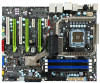
...See Appendix A. For USB Port Cable 17. 1394a connector - With integrated HDD activity LED 20. For use with Active Cooling - EVGA nForce 790i SLI FTW Motherboard Layout CPU Socket - nForce 790i SLI SPP with a system chassis 14. Connect CPU Fan to this ... Front panel connector - Serial connector - For Intel LGA 775 CPUs 2. Easily clears the system BIOS 16. Floppy Disk Drive Connector 9. Backpanel connectors (Figure 2) 26. Helps retain system BIOS settings Figure 1. For PCI based components 22. Exclusive for SLI configurations 23. For Firewire Port Cable...
...See Appendix A. For USB Port Cable 17. 1394a connector - With integrated HDD activity LED 20. For use with Active Cooling - EVGA nForce 790i SLI FTW Motherboard Layout CPU Socket - nForce 790i SLI SPP with a system chassis 14. Connect CPU Fan to this ... Front panel connector - Serial connector - For Intel LGA 775 CPUs 2. Easily clears the system BIOS 16. Floppy Disk Drive Connector 9. Backpanel connectors (Figure 2) 26. Helps retain system BIOS settings Figure 1. For PCI based components 22. Exclusive for SLI configurations 23. For Firewire Port Cable...
User Guide
Page 34
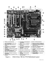
The POWER button with LED indicates the activity status of the hard disks. When the system is in the bios. When the system is powered on . The CMOS can be cleared by using the following procedure: Turn off the system, and conveniently clear the CMOS. ...
The POWER button with LED indicates the activity status of the hard disks. When the system is in the bios. When the system is powered on . The CMOS can be cleared by using the following procedure: Turn off the system, and conveniently clear the CMOS. ...
User Guide
Page 36
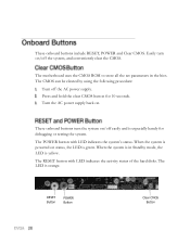
This section includes the following information: Enter BIOS Setup Main Menu Standard CMOS Features Advanced BIOS Features Advanced Chipset Features Integrated Peripherals Power Management Setup PnP/PCI Configurations PC Health Status Frequency/Voltage Control This section discusses how to change the system settings through the BIOS Setup menus. Detailed descriptions of the BIOS parameters are also provided.
This section includes the following information: Enter BIOS Setup Main Menu Standard CMOS Features Advanced BIOS Features Advanced Chipset Features Integrated Peripherals Power Management Setup PnP/PCI Configurations PC Health Status Frequency/Voltage Control This section discusses how to change the system settings through the BIOS Setup menus. Detailed descriptions of the BIOS parameters are also provided.

User Guide
Page 37
... menu allows you choose. To go back to select from the list of the screen during the Power On Self Test (POST). Power on the BIOS screens all data in white is for information only, data in yellow is changeable, data in blue is non-changeable, and data in the option... Esc. Use the Page Up and Page Down keys to scroll through the options or press Enter to maintain optimal system performance. Correctly setting the BIOS parameters is highlighted for selection. Press F1 to continue, DEL to position the selector in a red box is critical to display the associated submenu. It...
... menu allows you choose. To go back to select from the list of the screen during the Power On Self Test (POST). Power on the BIOS screens all data in white is for information only, data in yellow is changeable, data in blue is non-changeable, and data in the option... Esc. Use the Page Up and Page Down keys to scroll through the options or press Enter to maintain optimal system performance. Correctly setting the BIOS parameters is highlighted for selection. Press F1 to continue, DEL to position the selector in a red box is critical to display the associated submenu. It...

User Guide
Page 38
... Defaults Load Optimized Defaults Set Supervisor Password Set User Password Save & Exit Setup Exit Without Saving Select Item Time, Date, Hard Disk Type.., Figure 5. ---- BIOS CMOS Setup Utility Main Menu Standard CMOS Features Use this menu to set up the basic system configuration. Advanced... BIOS Features Use this menu to set up the advanced system features and boot sequence. Advanced Chipset Features Use this menu to optimize system...
... Defaults Load Optimized Defaults Set Supervisor Password Set User Password Save & Exit Setup Exit Without Saving Select Item Time, Date, Hard Disk Type.., Figure 5. ---- BIOS CMOS Setup Utility Main Menu Standard CMOS Features Use this menu to set up the basic system configuration. Advanced... BIOS Features Use this menu to set up the advanced system features and boot sequence. Advanced Chipset Features Use this menu to optimize system...
User Guide
Page 39
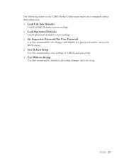
The following items on the CMOS Setup Utility main menu are commands rather than submenus: Load Fail-Safe Defaults Load Fail-Safe defaults system settings. Load Optimized Defaults Load Optimized defaults system settings. Set Supervisor Password/Set User Password Use this command to set, change, and disable the password used to access the BIOS menu. Save & Exit Setup Use this command to save settings to CMOS and exit setup. Exit Without Saving Use this command to abandon all setting changes and exit setup.
The following items on the CMOS Setup Utility main menu are commands rather than submenus: Load Fail-Safe Defaults Load Fail-Safe defaults system settings. Load Optimized Defaults Load Optimized defaults system settings. Set Supervisor Password/Set User Password Use this command to set, change, and disable the password used to access the BIOS menu. Save & Exit Setup Use this command to save settings to CMOS and exit setup. Exit Without Saving Use this command to abandon all setting changes and exit setup.
User Guide
Page 42
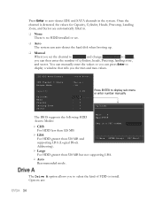
Press Enter to display sub-menu or enter number manually Cylinder The BIOS supports the following HDD Access Modes: CHS Min= 0 Max=65535 Key in a DEC number : For HDD less than 528 MB. LBA For HDD ...
Press Enter to display sub-menu or enter number manually Cylinder The BIOS supports the following HDD Access Modes: CHS Min= 0 Max=65535 Key in a DEC number : For HDD less than 528 MB. LBA For HDD ...
User Guide
Page 43
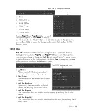
...] Press ENTER to the Standard CMOS Features menu. Press Enter to accept the changes and return to display sub-menu All Errors Whenever the BIOS detects a nonfatal error, the system stops and prompts you choose.
...] Press ENTER to the Standard CMOS Features menu. Press Enter to accept the changes and return to display sub-menu All Errors Whenever the BIOS detects a nonfatal error, the system stops and prompts you choose.

User Guide
Page 44
These settings are display-only values that are determined by the BIOS POST (Power-On Self Test). Base Memory 640K Base Memory BIOS POST determines the Extended Memory Total Memory 1047552K 1048576K amount of base (or conventional) memory installed in the system. Extended Memory BIOS determines how much extended memory is present during the POST. Total Memory This value represents the total memory of the system.
These settings are display-only values that are determined by the BIOS POST (Power-On Self Test). Base Memory 640K Base Memory BIOS POST determines the Extended Memory Total Memory 1047552K 1048576K amount of base (or conventional) memory installed in the system. Extended Memory BIOS determines how much extended memory is present during the POST. Total Memory This value represents the total memory of the system.
User Guide
Page 45
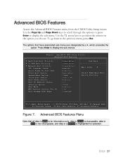
... by a , which precedes the option. Phoenix - The options that all data in white is for selection. AwardBIOS CMOS Setup Utility Advanced BIOS Features Hard Disk Boot Priority CD-ROM Boot Priority Network Boot Priority CPU Internal Cache Quick Power On Self Test ...:Fail-Safe Defaults F7:Optimized Defaults Figure 7. Use the arrow keys to the previous menu, press Esc. Access the Advanced BIOS Features menu from the CMOS Utility Setup screen. To go back to position the selector in a red box is highlighted for information only, ...
... by a , which precedes the option. Phoenix - The options that all data in white is for selection. AwardBIOS CMOS Setup Utility Advanced BIOS Features Hard Disk Boot Priority CD-ROM Boot Priority Network Boot Priority CPU Internal Cache Quick Power On Self Test ...:Fail-Safe Defaults F7:Optimized Defaults Figure 7. Use the arrow keys to the previous menu, press Esc. Access the Advanced BIOS Features menu from the CMOS Utility Setup screen. To go back to position the selector in a red box is highlighted for information only, ...

User Guide
Page 48
... Down keys to access the CMOS Setup screen and when the system boots. Use this function to select the Multi-Processor Specification (MPS) version that BIOS passes to enable or disable the Advanced Programmable Interrupt Controller (APIC). Select System to require a password to toggle between Enable and Disable Use the Page...
... Down keys to access the CMOS Setup screen and when the system boots. Use this function to select the Multi-Processor Specification (MPS) version that BIOS passes to enable or disable the Advanced Programmable Interrupt Controller (APIC). Select System to require a password to toggle between Enable and Disable Use the Page...
User Guide
Page 49
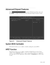
... used . Select Advanced Chipset Features from the CMOS Setup Utility menu and press Enter to enable or disable caching the system BIOS. AwardBIOS CMOS Setup Utility Advanced Chipset Features System BIOS Cacheable HPET Function [Disabled] [Enable] Item Help Main Level Move Enter:Select +/-/PU/PD:Value F10:Save ESC:Exit F1...
... used . Select Advanced Chipset Features from the CMOS Setup Utility menu and press Enter to enable or disable caching the system BIOS. AwardBIOS CMOS Setup Utility Advanced Chipset Features System BIOS Cacheable HPET Function [Disabled] [Enable] Item Help Main Level Move Enter:Select +/-/PU/PD:Value F10:Save ESC:Exit F1...
User Guide
Page 58
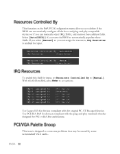
...-and-play compatible devices or if you can manually select IRQ, DMA, and memory base address fields. If you select [Manual] so you want the BIOS to automatically populate these fields. This item is enabled for input. Use PCI/ISA PnP for devices compliant with the original PC AT Bus specification.... This function on the PnP/PCI Configuration menu allows you to define if the BIOS can automatically configure all the boot and plug-and-play standard, whether designed for PCI or ISA Bus architecture.
...-and-play compatible devices or if you can manually select IRQ, DMA, and memory base address fields. If you select [Manual] so you want the BIOS to automatically populate these fields. This item is enabled for input. Use PCI/ISA PnP for devices compliant with the original PC AT Bus specification.... This function on the PnP/PCI Configuration menu allows you to define if the BIOS can automatically configure all the boot and plug-and-play standard, whether designed for PCI or ISA Bus architecture.
User Guide
Page 63
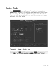
..., MHz [Auto] 100 PCIe x16_3, MHz [Auto] 100 SPPMCP Ref Clock, MHz [Auto] 100 **HT Multiplier** nForce SPP --> nForce MCP [5 x] nForce SPP On the actual BIOS screen, you are listed. From this menu, you will need to scroll down to see all of the options are able to display the System...
..., MHz [Auto] 100 PCIe x16_3, MHz [Auto] 100 SPPMCP Ref Clock, MHz [Auto] 100 **HT Multiplier** nForce SPP --> nForce MCP [5 x] nForce SPP On the actual BIOS screen, you are listed. From this menu, you will need to scroll down to see all of the options are able to display the System...
User Guide
Page 76
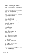
... Module DRAM - Digital Video Interface FDC - Dry Ice Cooling DDR2 - Front Side Bus FTW - ACPI - Advanced Configuration and Power Interface AFR - Advanced Programmable Interrupt Controller BIOS - Double Data Rate 3 DIMM - GHz - Gigahertz GPU - Graphics Processing Unit HDD - Hard Disk Drive HDMI - High-Definition Multimedia Interface HDR - High Precision Event Timer HSF...
... Module DRAM - Digital Video Interface FDC - Dry Ice Cooling DDR2 - Front Side Bus FTW - ACPI - Advanced Configuration and Power Interface AFR - Advanced Programmable Interrupt Controller BIOS - Double Data Rate 3 DIMM - GHz - Gigahertz GPU - Graphics Processing Unit HDD - Hard Disk Drive HDMI - High-Definition Multimedia Interface HDR - High Precision Event Timer HSF...
User Guide
Page 79
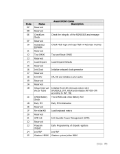
... 1C 1D 1E 1F 20 21 22 23 24 25 Name Reserved Award POST Codes Description Reserved CheckSum Check Check the integrity of the ROM,BIOS and message Reserved Autodetect EEPROM Check Flash type and copy flash write/erase routines Reserved Test CMOS Test and Reset CMOS Reserved Load Chipset Load... Reserved HPM init Init Heuristic Power Management (HPM) Reserved Program chipset Early Programming of chipset registers Init PNP Init PNP Shadow VBIOS Shadow system/video BIOS
... 1C 1D 1E 1F 20 21 22 23 24 25 Name Reserved Award POST Codes Description Reserved CheckSum Check Check the integrity of the ROM,BIOS and message Reserved Autodetect EEPROM Check Flash type and copy flash write/erase routines Reserved Test CMOS Test and Reset CMOS Reserved Load Chipset Load... Reserved HPM init Init Heuristic Power Management (HPM) Reserved Program chipset Early Programming of chipset registers Init PNP Init PNP Shadow VBIOS Shadow system/video BIOS
User Guide
Page 80
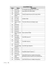
... DMA Page Registers Reserved Reserved Test Timer Reserved Test 8259-1 Mask Reserved Test 8259-2 Award POST Codes Description Init onboard clock generator and sensor Setup BIOS DATA AREA (BDA) Chipset programming and CPU Speed detect Initialize Video Test Video Memory and display Logos Early Keyboard Reset Test DMA channel 0 Test DMA...
... DMA Page Registers Reserved Reserved Test Timer Reserved Test 8259-1 Mask Reserved Test 8259-2 Award POST Codes Description Init onboard clock generator and sensor Setup BIOS DATA AREA (BDA) Chipset programming and CPU Speed detect Initialize Video Test Video Memory and display Logos Early Keyboard Reset Test DMA channel 0 Test DMA...
User Guide
Page 82
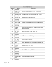
... PS2 Mouse port ACPI sub-system initializing Initialize cache controller Enter setup check and autoconfiguration check up Initialize floppy disk drive Install FDD and setup BIOS data area parameters Initialize hard drive controller Special treatment to Protect Setup If required, will auto load Awdflash.exe in POST Init Initializing onboard superIO...
... PS2 Mouse port ACPI sub-system initializing Initialize cache controller Enter setup check and autoconfiguration check up Initialize floppy disk drive Install FDD and setup BIOS data area parameters Initialize hard drive controller Special treatment to Protect Setup If required, will auto load Awdflash.exe in POST Init Initializing onboard superIO...
