User Guide
Page 8
... cables provided in a PC case, it does not contain the following items that must be purchased separately to install and connect your new EVGA nForce® 790i SLI FTW motherboard. However, it is highly recommended to allow for proper system functionality. If however, you are building a PC, you have purchased all necessary...
... cables provided in a PC case, it does not contain the following items that must be purchased separately to install and connect your new EVGA nForce® 790i SLI FTW motherboard. However, it is highly recommended to allow for proper system functionality. If however, you are building a PC, you have purchased all necessary...
User Guide
Page 9
This motherboard offers the tools, performance, and overclocking potential that PC Enthusiasts demand. Supports up to 8 GBs of 12 inches x 9.6 inches Microprocessor support Intel Core 2 Extreme, ... from S1 and S3 mode Supports USB 2.0 protocol up to 480 Mbps transmission rate Thank you get innovative NVIDIA SLI Technology for purchasing the EVGA nForce 790i SLI FTW Motherboard.
This motherboard offers the tools, performance, and overclocking potential that PC Enthusiasts demand. Supports up to 8 GBs of 12 inches x 9.6 inches Microprocessor support Intel Core 2 Extreme, ... from S1 and S3 mode Supports USB 2.0 protocol up to 480 Mbps transmission rate Thank you get innovative NVIDIA SLI Technology for purchasing the EVGA nForce 790i SLI FTW Motherboard.
User Guide
Page 11
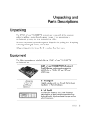
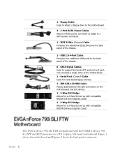
... and MCP and is missing or damaged, contact your reseller. The EVGA nForce 790i SLI FTW motherboard comes with all the necessary cables for adding a motherboard to inspect each piece of equipment shipped in the packing box. Be... radio frequency transmissions, protect internal components from dust and foreign objects and aids in this kit are replacing a motherboard, you through the hardware installation of these cables. If you are RoHS-compliant (lead-free) parts. All ...visually guide you may not need many of the motherboard. 1 - I/O Shield Installs in the EVGA nForce 790i SLI FTW...
... and MCP and is missing or damaged, contact your reseller. The EVGA nForce 790i SLI FTW motherboard comes with all the necessary cables for adding a motherboard to inspect each piece of equipment shipped in the packing box. Be... radio frequency transmissions, protect internal components from dust and foreign objects and aids in this kit are replacing a motherboard, you through the hardware installation of these cables. If you are RoHS-compliant (lead-free) parts. All ...visually guide you may not need many of the motherboard. 1 - I/O Shield Installs in the EVGA nForce 790i SLI FTW...
User Guide
Page 12
... panel of the chassis. 1 - Serial Port (Comm2) Cable Used for a 3-Way SLI set up with compatible NVIDA GeForce Graphics Cards The EVGA nForce 790i SLI FTW motherboard with compatible NVIDA GeForce Graphics Cards 1 - 3-Way SLI Bridge Allows for serial based legacy devices 1 - 1 - IDE-ATA 133 HDD Cable... Passes data between the IDE connection on the motherboard and IDE device. 1 - 2-Way SLI Bridge Allows for a 2-Way SLI set up with the NVIDIA nForce 790i SLI SPP and MCP processors is a...
... panel of the chassis. 1 - Serial Port (Comm2) Cable Used for a 3-Way SLI set up with compatible NVIDA GeForce Graphics Cards The EVGA nForce 790i SLI FTW motherboard with compatible NVIDA GeForce Graphics Cards 1 - 3-Way SLI Bridge Allows for serial based legacy devices 1 - 1 - IDE-ATA 133 HDD Cable... Passes data between the IDE connection on the motherboard and IDE device. 1 - 2-Way SLI Bridge Allows for a 2-Way SLI set up with the NVIDIA nForce 790i SLI SPP and MCP processors is a...
User Guide
Page 13
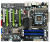
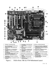
... connector - SPDIF connector - Passive heatsink for devices that require a PCI-E x1 slot 24. CPU 8-Pin Power connector 28. MCP/SPP fan connector - Motherboard CMOS Battery - EVGA nForce 790i SLI FTW Motherboard Layout CPU fan connector - Main Power Connection 6. IDE connector - NVIDIA MCP (passive heat sink) - For Hi-Definition Audio 13. Front panel connector...
... connector - SPDIF connector - Passive heatsink for devices that require a PCI-E x1 slot 24. CPU 8-Pin Power connector 28. MCP/SPP fan connector - Motherboard CMOS Battery - EVGA nForce 790i SLI FTW Motherboard Layout CPU fan connector - Main Power Connection 6. IDE connector - NVIDIA MCP (passive heat sink) - For Hi-Definition Audio 13. Front panel connector...

User Guide
Page 15
The topics covered in this section are: Preparing the motherboard Installing the CPU Installing the CPU fan Installing the memory Installing the motherboard Connecting cables and setting switches To reduce the risk of the motherboard. Remember to remove power from your computer by disconnecting the AC main source before removing or installing any equipment from/to the computer chassis. This section will guide you through the installation of fire, electric shock, and injury always follow basic safety precautions.
The topics covered in this section are: Preparing the motherboard Installing the CPU Installing the CPU fan Installing the memory Installing the motherboard Connecting cables and setting switches To reduce the risk of the motherboard. Remember to remove power from your computer by disconnecting the AC main source before removing or installing any equipment from/to the computer chassis. This section will guide you through the installation of fire, electric shock, and injury always follow basic safety precautions.
User Guide
Page 16
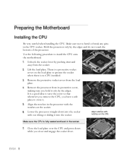
... in the processor with notches on the CPU Make sure the CPU is no CPU installed. Make sure not to install the CPU onto the motherboard. Hold the processor only by pushing down and away from the socket. It is a good idea to save the cover so that whenever you remove...
... in the processor with notches on the CPU Make sure the CPU is no CPU installed. Make sure not to install the CPU onto the motherboard. Hold the processor only by pushing down and away from the socket. It is a good idea to save the cover so that whenever you remove...

User Guide
Page 17
There are many different fan types that came with this motherboard. Your new motherboard has four 240-pin slots for the location of the memory slots.) For memory over 1600MHz(PC3 12800) use slots 2 and 3 (black). One DIMM: ...
There are many different fan types that came with this motherboard. Your new motherboard has four 240-pin slots for the location of the memory slots.) For memory over 1600MHz(PC3 12800) use slots 2 and 3 (black). One DIMM: ...
User Guide
Page 18
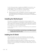
...center of the DIMM slot automatically lock the DIMM into the chassis depends on the covers. Press the I /O shield and secure the motherboard into place and make sure it would need to block radio frequency transmissions, protects internal components from dust and foreign objects, and promotes... into the chassis. Align the memory module to the DIMM slot and insert the module vertically while applying light downward pressure to secure the motherboard first. If the I /O shield that the CPU fan assembly has enough clearance for the expansion cards. It is used to obtain the...
...center of the DIMM slot automatically lock the DIMM into the chassis depends on the covers. Press the I /O shield and secure the motherboard into place and make sure it would need to block radio frequency transmissions, protects internal components from dust and foreign objects, and promotes... into the chassis. Align the memory module to the DIMM slot and insert the module vertically while applying light downward pressure to secure the motherboard first. If the I /O shield that the CPU fan assembly has enough clearance for the expansion cards. It is used to obtain the...
User Guide
Page 19
... is aligned with the studs/spacers. Ensure that do not align with a mounting hole on the motherboard. If there are stud(s) that the fan assembly is recommended to secure the motherboard using a minimum of eight (8) to ten (10) studs. In most cases, it is recommended that you remove that ...stud(s) to prevent the possibility of a short circuit. Align the connectors to the I/O shield. Secure the motherboard with mounting studs or spacers to allow the mother board to be secured to the chassis and help to prevent short circuits. This will include...
... is aligned with the studs/spacers. Ensure that do not align with a mounting hole on the motherboard. If there are stud(s) that the fan assembly is recommended to secure the motherboard using a minimum of eight (8) to ten (10) studs. In most cases, it is recommended that you remove that ...stud(s) to prevent the possibility of a short circuit. Align the connectors to the I/O shield. Secure the motherboard with mounting studs or spacers to allow the mother board to be secured to the chassis and help to prevent short circuits. This will include...

User Guide
Page 20
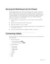
... See Figure 1 on page 5 to locate the connectors and button referenced in either of the following procedure. Power Supply Connectors To support 3-way SLI, this motherboard has the following specific power supply requirements: Minimum 1000 W peak power Six PCI-E power connectors configured in the following configurations (see Figure 3): ...
... See Figure 1 on page 5 to locate the connectors and button referenced in either of the following procedure. Power Supply Connectors To support 3-way SLI, this motherboard has the following specific power supply requirements: Minimum 1000 W peak power Six PCI-E power connectors configured in the following configurations (see Figure 3): ...

User Guide
Page 21
... along the edge of the board next to the DIMM slots. PWR1 connector Plug power cable from power supply to PWR1 Board edge Figure 4. PWR1 Motherboard Connector Table 1. To determine what you will be installing. PWR1 is secure. Make sure that the power supply cable and pins are for your specific... 24 GND Make sure you have enough power to cover all the expansion cards you power requirements are properly aligned with the connector on the motherboard.
... along the edge of the board next to the DIMM slots. PWR1 connector Plug power cable from power supply to PWR1 Board edge Figure 4. PWR1 Motherboard Connector Table 1. To determine what you will be installing. PWR1 is secure. Make sure that the power supply cable and pins are for your specific... 24 GND Make sure you have enough power to cover all the expansion cards you power requirements are properly aligned with the connector on the motherboard.
User Guide
Page 22
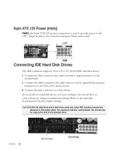
... drives. Connect the blue connector (the cable end with two closely spaced black and grey connectors) to that of the slowest drive. Refer to the motherboard. Align the pins to the connector and press firmly until seated. IDE Connector
... drives. Connect the blue connector (the cable end with two closely spaced black and grey connectors) to that of the slowest drive. Refer to the motherboard. Align the pins to the connector and press firmly until seated. IDE Connector
User Guide
Page 23
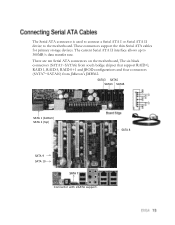
... connectors support the thin Serial ATA cables for primary storage devices. There are ten Serial ATA connectors on the motherboard, The six black connectors (SATA1~SATA6) from south bridge chipset that support RAID 0, RAID 1, RAID 5, RAID 0+1 and JBOD configurations and four connectors (SATA7~SATA10) from ...
... connectors support the thin Serial ATA cables for primary storage devices. There are ten Serial ATA connectors on the motherboard, The six black connectors (SATA1~SATA6) from south bridge chipset that support RAID 0, RAID 1, RAID 5, RAID 0+1 and JBOD configurations and four connectors (SATA7~SATA10) from ...
User Guide
Page 24
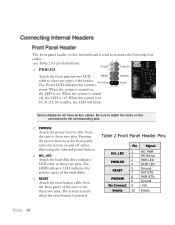
... button on the front panel turns the system on and off . Some chassis do not have all four cables. The front panel header on this motherboard is used to connect the following four cables. (see Table 2 for pin definitions): PWRLED Attach the front panel power LED cable to these two...
... button on the front panel turns the system on and off . Some chassis do not have all four cables. The front panel header on this motherboard is used to connect the following four cables. (see Table 2 for pin definitions): PWRLED Attach the front panel power LED cable to these two...
User Guide
Page 25
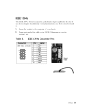
IEEE 1394a Connector Pins Connector IEEE 1394a Connector 10 9 8 7 6 5 4 3 2 1 Pin 1 2 3 4 5 6 7 8 9 10 Signal TPA+ TPAGND GND TPB+ TPB+12V +12V Empty GND Table 3. The IEEE 1394a (Firewire) expansion cable bracket is provided in the box but if you do not require the additional external connections, you do not need to the IEEE 1394a connector on the motherboard. Connect the end of your chassis. Secure the bracket to the rear panel of the cable to install it.
IEEE 1394a Connector Pins Connector IEEE 1394a Connector 10 9 8 7 6 5 4 3 2 1 Pin 1 2 3 4 5 6 7 8 9 10 Signal TPA+ TPAGND GND TPB+ TPB+12V +12V Empty GND Table 3. The IEEE 1394a (Firewire) expansion cable bracket is provided in the box but if you do not require the additional external connections, you do not need to the IEEE 1394a connector on the motherboard. Connect the end of your chassis. Secure the bracket to the rear panel of the cable to install it.
User Guide
Page 26
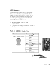
Secure the bracket to the USB 2.0 headers on the rear panel of your chassis. Table 4. USB 2.0 Header Pins Connector USB 2.0 Header Connector Pin 1 3 5 7 9 Pin 2 4 6 8 10 Signal 5V_DUAL DataData+ GND Empty Signal 5V_DUAL DataData+ GND No Connect This motherboard contains six (6) USB 2.0 ports that can be used to connect an optional external bracket containing four (4) USB 2.0 ports. The motherboard also contains two 10pin internal header connectors onboard that are exposed on the motherboard. Connect the two ends of the cables to the rear panel of the chassis (Figure 2).
Secure the bracket to the USB 2.0 headers on the rear panel of your chassis. Table 4. USB 2.0 Header Pins Connector USB 2.0 Header Connector Pin 1 3 5 7 9 Pin 2 4 6 8 10 Signal 5V_DUAL DataData+ GND Empty Signal 5V_DUAL DataData+ GND No Connect This motherboard contains six (6) USB 2.0 ports that can be used to connect an optional external bracket containing four (4) USB 2.0 ports. The motherboard also contains two 10pin internal header connectors onboard that are exposed on the motherboard. Connect the two ends of the cables to the rear panel of the chassis (Figure 2).
User Guide
Page 30
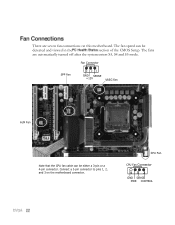
The fan speed can be detected and viewed in the section of the CMOS Setup. Connect a 3-pin connector to pins 1, 2, and 3 on this motherboard. The fans are seven fan connections on the motherboard connector. Fan Connector SPP Fan 3 21 GND SENSE +12V VREG Fan AUX Fan Note that the CPU fan cable can be either a 3-pin or a 4-pin connector. CPU Fan CPU Fan Connector 4 3 2 GN1D SENSE PWR CONTROL There are automatically turned off after the system enters S3, S4 and S5 mode.
The fan speed can be detected and viewed in the section of the CMOS Setup. Connect a 3-pin connector to pins 1, 2, and 3 on this motherboard. The fans are seven fan connections on the motherboard connector. Fan Connector SPP Fan 3 21 GND SENSE +12V VREG Fan AUX Fan Note that the CPU fan cable can be either a 3-pin or a 4-pin connector. CPU Fan CPU Fan Connector 4 3 2 GN1D SENSE PWR CONTROL There are automatically turned off after the system enters S3, S4 and S5 mode.

User Guide
Page 31
System fan connector Fan Connector 3 2 1 GND +12V SENSE Chassis fan connector Chassis fan connector The motherboard kit provides a serial COM port bracket for your system. Connect one side of the cable to the header and then attach the serial COM device to the other side of the cable.
System fan connector Fan Connector 3 2 1 GND +12V SENSE Chassis fan connector Chassis fan connector The motherboard kit provides a serial COM port bracket for your system. Connect one side of the cable to the header and then attach the serial COM device to the other side of the cable.
User Guide
Page 32
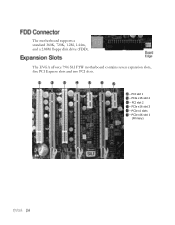
PCI slot 2 - PCIe x16 slot 3 - PCIe x16 slot 2 - PCI slot 1 - PCIe x1 slots - The EVGA nForce 790i SLI FTW motherboard contains seven expansion slots, five PCI Express slots and two PCI slots. 1 2 3 4 5 6 5 - The motherboard supports a standard 360K, 720K, 1.2M, 1.44m, and a 2.88M floppy disk drive (FDD). PCIe x16 slot 1 (Primary)
PCI slot 2 - PCIe x16 slot 3 - PCIe x16 slot 2 - PCI slot 1 - PCIe x1 slots - The EVGA nForce 790i SLI FTW motherboard contains seven expansion slots, five PCI Express slots and two PCI slots. 1 2 3 4 5 6 5 - The motherboard supports a standard 360K, 720K, 1.2M, 1.44m, and a 2.88M floppy disk drive (FDD). PCIe x16 slot 1 (Primary)