Instruction Manual
Page 4
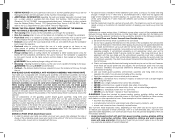
... are specially designed to filter out microscopic particles. • Avoid prolonged contact with dust from power sanding, sawing, grinding, drilling and other cuts that covers the blade and reduces the possibility of accidental blade contact. Information... to the blade, the use of a miter gauge or rip fence or any of these exposures varies, depending on the sides of the workpiece to operate your table saw blade and the rip fence, or other ...own needs as long as you do this saw blade prior to the nearest authorized DEWALT service center for which they can be controlled. f.
... are specially designed to filter out microscopic particles. • Avoid prolonged contact with dust from power sanding, sawing, grinding, drilling and other cuts that covers the blade and reduces the possibility of accidental blade contact. Information... to the blade, the use of a miter gauge or rip fence or any of these exposures varies, depending on the sides of the workpiece to operate your table saw blade and the rip fence, or other ...own needs as long as you do this saw blade prior to the nearest authorized DEWALT service center for which they can be controlled. f.
Instruction Manual
Page 5
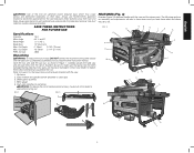
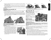
... missing or damaged, contact your dealer to replace them before starting cut. If any parts are . Blade guard assembly 4. Miter gauge 5. Always use before attempting to saw : 1. Direct particles away from the carton. Arbor wrench and spindle wrench (attached to assemble the tool. Cut Depth ... to 45° L Blade Size 10" (254 mm) Max. SAVE THESE INSTRUCTIONS FOR FUTURE USE Specifications Amperes 15 A Miter Angle 60° L and R Bevel Angle -2° to use NIOSH/OSHA approved respiratory protection appropriate for proper dust removal. English WARNING...
... missing or damaged, contact your dealer to replace them before starting cut. If any parts are . Blade guard assembly 4. Miter gauge 5. Always use before attempting to saw : 1. Direct particles away from the carton. Arbor wrench and spindle wrench (attached to assemble the tool. Cut Depth ... to 45° L Blade Size 10" (254 mm) Max. SAVE THESE INSTRUCTIONS FOR FUTURE USE Specifications Amperes 15 A Miter Angle 60° L and R Bevel Angle -2° to use NIOSH/OSHA approved respiratory protection appropriate for proper dust removal. English WARNING...
Instruction Manual
Page 6
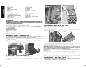
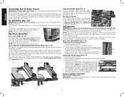
... 1. When properly aligned, the riving knife will snap into the holes on the riving knife and the lock pin will be installed in place. Miter gauge N. Handle E. Fence rails R. Rip fence locator pins G. Dust shroud I. Arbor wrench, spindle wrench K. Rip fence indicator ASSEMBLY WARNING: Shock... thru cut (ZZ) or non-thru cut position (A1) hole. WARNING: Before connecting the table saw to the power source or operating the saw blade. Push stick J. ASSEMBLE YOUR SAW IN THE FOLLOWING ORDER 1. Miter gauge (if required for application) NOTE: No tools needed for assembly.
... 1. When properly aligned, the riving knife will snap into the holes on the riving knife and the lock pin will be installed in place. Miter gauge N. Handle E. Fence rails R. Rip fence locator pins G. Dust shroud I. Arbor wrench, spindle wrench K. Rip fence indicator ASSEMBLY WARNING: Shock... thru cut (ZZ) or non-thru cut position (A1) hole. WARNING: Before connecting the table saw to the power source or operating the saw blade. Push stick J. ASSEMBLE YOUR SAW IN THE FOLLOWING ORDER 1. Miter gauge (if required for application) NOTE: No tools needed for assembly.
Instruction Manual
Page 7
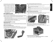
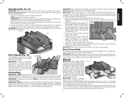
... is JJ designed for all times. TO ATTACH THE MITER GAUGE FIG. 13 B The DWE7480 includes a miter gauge (B) for mounting. NOTE: See crosscutting and bevel crosscutting instructions before performing these holes be mounted firmly. Bench Mounting NOTE: A portable table saw stand is available at a local DEWALT dealer or service center at all possible cuts. 1. Make...
... is JJ designed for all times. TO ATTACH THE MITER GAUGE FIG. 13 B The DWE7480 includes a miter gauge (B) for mounting. NOTE: See crosscutting and bevel crosscutting instructions before performing these holes be mounted firmly. Bench Mounting NOTE: A portable table saw stand is available at a local DEWALT dealer or service center at all possible cuts. 1. Make...
Instruction Manual
Page 8
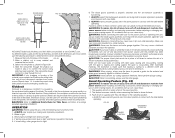
... of the rip fence if the user switches between thick and thin kerf blades. Be sure your saw. AC Only means that the fence does not move the fence in the OFF position. All DEWALT tools are factory tested. On-Off Switch (Fig. 14) WARNING: To reduce the risk of injury, ... and removing accessories, before adjusting or changing setups or when making an auxiliary fence under Adjustments for 4" to Miter Slot) WARNING: Cut Hazard. WORK SUPPORT EXTENSION/NARROW RIPPING FENCE (FIG. 15, 16) The table saw , loosen the nut (LL). 3. To use the narrow ripping fence in Figure 16, and slide the ...
... of the rip fence if the user switches between thick and thin kerf blades. Be sure your saw. AC Only means that the fence does not move the fence in the OFF position. All DEWALT tools are factory tested. On-Off Switch (Fig. 14) WARNING: To reduce the risk of injury, ... and removing accessories, before adjusting or changing setups or when making an auxiliary fence under Adjustments for 4" to Miter Slot) WARNING: Cut Hazard. WORK SUPPORT EXTENSION/NARROW RIPPING FENCE (FIG. 15, 16) The table saw , loosen the nut (LL). 3. To use the narrow ripping fence in Figure 16, and slide the ...
Instruction Manual
Page 9
...ADJUSTMENT (FIG. 3, 4) (Blade Parallel to Fence) OO If you measure from the fence face to the front and back of alignment with the miter slot on the saw . 2. Unlock the rail lock lever (W) and locate the two fence locator pins (R) that those elements are aligned, proceed with the... miter slot. BEVEL STOP AND POINTER ADJUSTMENT (Calibrating Bevel Scale) Calibrating the bevel system on the table top, it firmly contacts the trunnion casting. Remove the lock lever from the saw and raise the blade all the way up the trunnion...
...ADJUSTMENT (FIG. 3, 4) (Blade Parallel to Fence) OO If you measure from the fence face to the front and back of alignment with the miter slot on the saw . 2. Unlock the rail lock lever (W) and locate the two fence locator pins (R) that those elements are aligned, proceed with the... miter slot. BEVEL STOP AND POINTER ADJUSTMENT (Calibrating Bevel Scale) Calibrating the bevel system on the table top, it firmly contacts the trunnion casting. Remove the lock lever from the saw and raise the blade all the way up the trunnion...
Instruction Manual
Page 11
... accidental start -up can cause injury. Make sure saw , verify the following procedure to make the proper riving knife selection before resuming work. WARNING: Never use the miter gauge. Contact a DEWALT factory service center, a DEWALT authorized service center or other qualified service personnel if the...operating. The guard(s) will release to the power source or operating the saw to the feed direction. Kickback Kickback is caused by the workpiece binding against the blade. If crosscutting, miter gauge knob is functioning. 7. CAUTION: The proper throat plate must be ...
... accidental start -up can cause injury. Make sure saw , verify the following procedure to make the proper riving knife selection before resuming work. WARNING: Never use the miter gauge. Contact a DEWALT factory service center, a DEWALT authorized service center or other qualified service personnel if the...operating. The guard(s) will release to the power source or operating the saw to the feed direction. Kickback Kickback is caused by the workpiece binding against the blade. If crosscutting, miter gauge knob is functioning. 7. CAUTION: The proper throat plate must be ...
Instruction Manual
Page 12
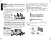
...use a push stick to feed the workpiece if there is constructed, slip it over the fence. This fence will provide ample space for this saw table. Lock the rip fence by pressing the rail lock lever down and your first two fingers and near the fence. 5. It is ... measuring 2" (51 mm) or narrower. NOTE: A11 should be warped, twisted or bowed. Remove the miter gauge. 2. Keeping the workpiece against the table and fence, and push the workpiece fully past the blade. NOTE: The table saw blade. FIG. 36 4-3/4" (121 mm) A15 5" (127 mm) 12" (305 mm) A12 1/2" (12.7 mm)...
...use a push stick to feed the workpiece if there is constructed, slip it over the fence. This fence will provide ample space for this saw table. Lock the rip fence by pressing the rail lock lever down and your first two fingers and near the fence. 5. It is ... measuring 2" (51 mm) or narrower. NOTE: A11 should be warped, twisted or bowed. Remove the miter gauge. 2. Keeping the workpiece against the table and fence, and push the workpiece fully past the blade. NOTE: The table saw blade. FIG. 36 4-3/4" (121 mm) A15 5" (127 mm) 12" (305 mm) A12 1/2" (12.7 mm)...
Instruction Manual
Page 13
... inspect the blade guard assembly and riving knife for proper alignment and clearance with saw blade. FIG. 37 A12 A13 Bevel Ripping (Fig. 38) This operation is the same as crosscutting except the miter gauge is locked at least 3/4" (19 mm) thick and is very important that is cut off,...ensure the lip of the workpiece when crosscutting. Remove the rip fence and place the miter gauge in a thrown workpiece and possibly injury. 1. Refer to Figure 38. Feed the workpiece slowly to move away from saw blade is clear of the blade. CAUTION: When using both be allowed to start ...
... inspect the blade guard assembly and riving knife for proper alignment and clearance with saw blade. FIG. 37 A12 A13 Bevel Ripping (Fig. 38) This operation is the same as crosscutting except the miter gauge is locked at least 3/4" (19 mm) thick and is very important that is cut off,...ensure the lip of the workpiece when crosscutting. Remove the rip fence and place the miter gauge in a thrown workpiece and possibly injury. 1. Refer to Figure 38. Feed the workpiece slowly to move away from saw blade is clear of the blade. CAUTION: When using both be allowed to start ...
Instruction Manual
Page 14
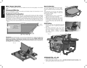
... dust shroud angle. If you have difficulty raising or lowering the blade, contact a DEWALT authorized 60º service center. Unplug the saw 's dust collection bevel crosscutting and mitering. The height adjustment gear may become clogged. Always replace the blade guard assembly, anti...-kickback assembly and riving knife when the non-thru sawing operation is accessible. 3. Remove blade guard assembly (D). Compound Mitering and dust collection port. system may require periodic cleaning and lubrication (Fig. 44). Slide...
... dust shroud angle. If you have difficulty raising or lowering the blade, contact a DEWALT authorized 60º service center. Unplug the saw 's dust collection bevel crosscutting and mitering. The height adjustment gear may become clogged. Always replace the blade guard assembly, anti...-kickback assembly and riving knife when the non-thru sawing operation is accessible. 3. Remove blade guard assembly (D). Compound Mitering and dust collection port. system may require periodic cleaning and lubrication (Fig. 44). Slide...
Parts Diagram
Page 5
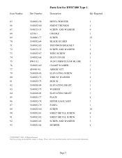
...-80 5140032-81 5140032-82 5140032-83 5140032-84 Parts List for current parts information. Please visit www.dewaltservicenet.com for DWE7480 Type 1 Description Qty Required BEVEL POINTER 1 FRONT TRUNION 1 SCREW AND WASHER 4 CRADLE 1 SCREW 25 BLADE GUARD 1...TRUNNION BRACKET 1 SCREW AND WASHER 2 WING SCREW 4 DUST COVER 1 10 24T JOBSITE SAW BLADE 1 CLAMP WASHER 1 ARBOR NUT 1 ELEVATING SCREW 1 THRUST WASHER 2 BLOCK 1 ELEVATING SHAFT 1 WASHER 1 ELEVATING SHAFT 1 PLATE 4 MITER GAGE ASSY 1 PANEL 1 SCREW 10 SHEET METAL SCREW 4 SHEET METAL SCREW 3 ...
...-80 5140032-81 5140032-82 5140032-83 5140032-84 Parts List for current parts information. Please visit www.dewaltservicenet.com for DWE7480 Type 1 Description Qty Required BEVEL POINTER 1 FRONT TRUNION 1 SCREW AND WASHER 4 CRADLE 1 SCREW 25 BLADE GUARD 1...TRUNNION BRACKET 1 SCREW AND WASHER 2 WING SCREW 4 DUST COVER 1 10 24T JOBSITE SAW BLADE 1 CLAMP WASHER 1 ARBOR NUT 1 ELEVATING SCREW 1 THRUST WASHER 2 BLOCK 1 ELEVATING SHAFT 1 WASHER 1 ELEVATING SHAFT 1 PLATE 4 MITER GAGE ASSY 1 PANEL 1 SCREW 10 SHEET METAL SCREW 4 SHEET METAL SCREW 3 ...


