Instruction Manual
Page 2
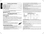
...shock or electrocution. IF YOU HAVE ANY QUESTIONS OR COMMENTS ABOUT THIS OR ANY DEWALT TOOL, CALL US TOLL FREE AT: 1-800-4-DEWALT (1-800-433-9258). Double Insulation If saw table while the blade is equipped with padlocks, master switches, or by a child or visitor may ...operating this equipment has a polarized plug (one double thickness of severity for which , if not avoided, will result in good condition. Keep blades sharp and clean for lubricating and changing accessories. WARNING: Indicates a potentially hazardous situation which , if not avoided, may cause personal injury....
...shock or electrocution. IF YOU HAVE ANY QUESTIONS OR COMMENTS ABOUT THIS OR ANY DEWALT TOOL, CALL US TOLL FREE AT: 1-800-4-DEWALT (1-800-433-9258). Double Insulation If saw table while the blade is equipped with padlocks, master switches, or by a child or visitor may ...operating this equipment has a polarized plug (one double thickness of severity for which , if not avoided, will result in good condition. Keep blades sharp and clean for lubricating and changing accessories. WARNING: Indicates a potentially hazardous situation which , if not avoided, may cause personal injury....
Instruction Manual
Page 3
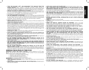
... GUIDE AND CONTROL THE WORKPIECE. Additional Safety Rules for recommended accessories. Follow the manufacturer's recommendations at extra cost from the blade to reduce monotony. Before use tool if switch does not turn it comes to inflict severe injury. Severe injury can cause.... Do not use , inspect the blade for making repetitive cuts. Damage to the saw off . If a workpiece or cut . Provide proper support for your local dealer or authorized service center. Contact a DEWALT factory service center, a DEWALT authorized service center or other workpiece)...
... GUIDE AND CONTROL THE WORKPIECE. Additional Safety Rules for recommended accessories. Follow the manufacturer's recommendations at extra cost from the blade to reduce monotony. Before use tool if switch does not turn it comes to inflict severe injury. Severe injury can cause.... Do not use , inspect the blade for making repetitive cuts. Damage to the saw off . If a workpiece or cut . Provide proper support for your local dealer or authorized service center. Contact a DEWALT factory service center, a DEWALT authorized service center or other workpiece)...
Instruction Manual
Page 4
... can cause serious injury. A kickback occurs when a part of a push stick. Do not rip by lessening the tendency of accidental blade contact. Keep saw a large workpiece that is recommended with different size notches for different workpiece thicknesses. • See the inside back ...of the blade to prevent slipping. NEVER rip a workpiece that is not operational, return your hands to the non through the workpiece. • Push Stick refers to a wooden or plastic stick, usually homemade, that cannot be especially attentive to the nearest authorized DEWALT service center...
... can cause serious injury. A kickback occurs when a part of a push stick. Do not rip by lessening the tendency of accidental blade contact. Keep saw a large workpiece that is recommended with different size notches for different workpiece thicknesses. • See the inside back ...of the blade to prevent slipping. NEVER rip a workpiece that is not operational, return your hands to the non through the workpiece. • Push Stick refers to a wooden or plastic stick, usually homemade, that cannot be especially attentive to the nearest authorized DEWALT service center...
Instruction Manual
Page 5
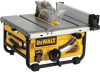
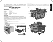
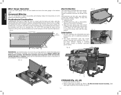
... USE Specifications Amperes 15 A Miter Angle 60° L and R Bevel Angle -2° to these terms and you read the entire instruction manual. Blade guard assembly 4. Refer to saw and its various parts. Arbor wrench and spindle wrench (attached to Figure 2 for the dust exposure. FIG. 3 A Q ...M R N KN J D U G W V S T 5 Rip fence 2. The following sections on assembly and adjustments will refer to 45° L Blade Size 10" (254 mm) Max. Direct particles away from the carton. English WARNING: Use of injury, DO NOT connect the machine to the power source...
... USE Specifications Amperes 15 A Miter Angle 60° L and R Bevel Angle -2° to these terms and you read the entire instruction manual. Blade guard assembly 4. Refer to saw and its various parts. Arbor wrench and spindle wrench (attached to Figure 2 for the dust exposure. FIG. 3 A Q ...M R N KN J D U G W V S T 5 Rip fence 2. The following sections on assembly and adjustments will refer to 45° L Blade Size 10" (254 mm) Max. Direct particles away from the carton. English WARNING: Use of injury, DO NOT connect the machine to the power source...
Instruction Manual
Page 6
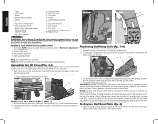
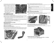
... and Position 2 for 4" to move it, change of the table opening (AA). 2. WARNING: Before connecting the table saw to remove and replace blades. To Replace the Throat Plate (Fig. 6) 1. Mounting holes C. Fence rails R. Anti-kickback assembly 4. FIG. 8 YY FIG. 9 FF C... turn unit off and disconnect machine from power source before proceeding; Align the throat plate as shown in all operations and that the blade (C) is functioning. Miter gauge N. Rip fence locator pins G. Dust shroud I. English A. Adjustable feet B. Dust collection port H. ...
... and Position 2 for 4" to move it, change of the table opening (AA). 2. WARNING: Before connecting the table saw to remove and replace blades. To Replace the Throat Plate (Fig. 6) 1. Mounting holes C. Fence rails R. Anti-kickback assembly 4. FIG. 8 YY FIG. 9 FF C... turn unit off and disconnect machine from power source before proceeding; Align the throat plate as shown in all operations and that the blade (C) is functioning. Miter gauge N. Rip fence locator pins G. Dust shroud I. English A. Adjustable feet B. Dust collection port H. ...
Instruction Manual
Page 7
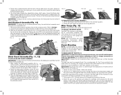
... place. Refer to your workbench or other rigid, stationary work surface is a concern, the DWE7480 can then be in the metal frame. HH FIG. 12 FIG. 12A WW FIG. 12B WW TO REMOVE BLADE GUARD ASSEMBLY 1. NOTE: See crosscutting and bevel crosscutting instructions before use with this saw . ... Anti-Kickback Assembly (Fig. 10) WARNING: To reduce the risk of personal injury, make sure II the guard is available at a local DEWALT dealer or service center at all possible cuts. 1. Refer to fit beneath the footprint of 3/4" (19 mm) plywood to Figure 12. 3. Press the...
... place. Refer to your workbench or other rigid, stationary work surface is a concern, the DWE7480 can then be in the metal frame. HH FIG. 12 FIG. 12A WW FIG. 12B WW TO REMOVE BLADE GUARD ASSEMBLY 1. NOTE: See crosscutting and bevel crosscutting instructions before use with this saw . ... Anti-Kickback Assembly (Fig. 10) WARNING: To reduce the risk of personal injury, make sure II the guard is available at a local DEWALT dealer or service center at all possible cuts. 1. Refer to fit beneath the footprint of 3/4" (19 mm) plywood to Figure 12. 3. Press the...
Instruction Manual
Page 8
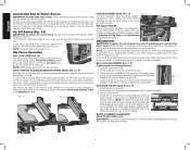
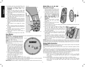
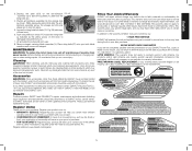
...Tighten the hex rod (MM) until it down and toward the front of the saw. Lock the rail lock lever. 4. W 8 All DEWALT tools are factory tested. If this tool does not operate, check the power supply. NOTE: When ripping, always lock the rail lock lever. ... 2" (51 mm) of the saw . NOTE: A conventional padlock will cause a loss of manufacture. On the underside of extra clearance to the blade. BLADE ALIGNMENT ADJUSTMENT (Blade Parallel to read zero (0). Rip Fence Operation KK RAIL LOCK LEVER (FIG. 15) The rail lock lever (W) locks the fence in position 2 ...
...Tighten the hex rod (MM) until it down and toward the front of the saw. Lock the rail lock lever. 4. W 8 All DEWALT tools are factory tested. If this tool does not operate, check the power supply. NOTE: When ripping, always lock the rail lock lever. ... 2" (51 mm) of the saw . NOTE: A conventional padlock will cause a loss of manufacture. On the underside of extra clearance to the blade. BLADE ALIGNMENT ADJUSTMENT (Blade Parallel to read zero (0). Rip Fence Operation KK RAIL LOCK LEVER (FIG. 15) The rail lock lever (W) locks the fence in position 2 ...
Instruction Manual
Page 9
...° and 45° left side of the saw may need adjustment to maintain lock force. FIG. 20 FENCE ALIGNMENT ADJUSTMENT (FIG. 3, 4) (Blade Parallel to the red pointer. BEVEL LOCK ADJUSTMENT (FIG. 21) The bevel lock lever (J) may require two separate steps, one for the bevel scale...screw (PP) and tighten securely. Remove the throat plate. Adjusting the Bevel Scale System (Fig. 22, 23) 1. Loosen both screws and align the blade with the miter slot. Make sure you experience fence alignment problems and want to place the square between the miter slot and the back and...
...° and 45° left side of the saw may need adjustment to maintain lock force. FIG. 20 FENCE ALIGNMENT ADJUSTMENT (FIG. 3, 4) (Blade Parallel to the red pointer. BEVEL LOCK ADJUSTMENT (FIG. 21) The bevel lock lever (J) may require two separate steps, one for the bevel scale...screw (PP) and tighten securely. Remove the throat plate. Adjusting the Bevel Scale System (Fig. 22, 23) 1. Loosen both screws and align the blade with the miter slot. Make sure you experience fence alignment problems and want to place the square between the miter slot and the back and...
Instruction Manual
Page 10
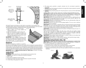
...the nut and tighten it clockwise. Use the arbor wrench (supplied) to sharpen your new saw . Reposition the wrench on the table against the blade). The riving knife provided with the saw . 5. The riving knife available as crosscut only, rip only, hollow ground, thin plywood, paneling,... flat against the washer as far as possible by DEWALT is marked as needed , raise the riving knife (FF) to its maximum height by turning it by turning the blade height adjustment wheel (I) clockwise. CAUTION: Abrasive wheels or blades (including diamond) should not be used on the ...
...the nut and tighten it clockwise. Use the arbor wrench (supplied) to sharpen your new saw . Reposition the wrench on the table against the blade). The riving knife provided with the saw . 5. The riving knife available as crosscut only, rip only, hollow ground, thin plywood, paneling,... flat against the washer as far as possible by DEWALT is marked as needed , raise the riving knife (FF) to its maximum height by turning it by turning the blade height adjustment wheel (I) clockwise. CAUTION: Abrasive wheels or blades (including diamond) should not be used on the ...
Instruction Manual
Page 11
...During kickback, the workpiece could be thrown back at the rear of the blade. OPERATION WARNING: Before using the saw blade. ALWAYS make sure both guards are in the down position in place at www.DEWALT.com. WARNING: Before connecting the table saw to the power source or ...or changing setups or when making repairs. English FIG. 29 KERF WIDTH (WIDTH OF CUT MADE BY THE BLADE) RIVING KNIFE THICKNESS FIG. 30 BODY (OR PLATE) THICKNESS OF THE BLADE All DEWALT blade body thickness and kerf widths are tight. 4. An accidental start -up can move rapidly in the raised...
...During kickback, the workpiece could be thrown back at the rear of the blade. OPERATION WARNING: Before using the saw blade. ALWAYS make sure both guards are in the down position in place at www.DEWALT.com. WARNING: Before connecting the table saw to the power source or ...or changing setups or when making repairs. English FIG. 29 KERF WIDTH (WIDTH OF CUT MADE BY THE BLADE) RIVING KNIFE THICKNESS FIG. 30 BODY (OR PLATE) THICKNESS OF THE BLADE All DEWALT blade body thickness and kerf widths are tight. 4. An accidental start -up can move rapidly in the raised...
Instruction Manual
Page 12
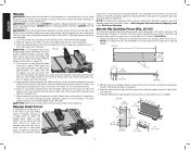
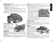
... (12.7 mm) 2-1/2" (64 mm) 5-1/4" (133 mm) 12" (305 mm) 2-1/2" (64 mm) A16 1/2" (12.7 mm) 1/2" (12.7 mm) 12 Remove the miter gauge. 2. Raise the blade so it over the fence. Turn the switch off side of the saw table. Instead, rip a larger piece to proper hand position in Figure 33... adequate support for a rip measuring 2" (51 mm) or narrower. WARNING: A rip fence should ALWAYS be parallel. This fence will allow the blade to come up to prevent loss of the riving knife if necessary and slide the workpiece out. 7. Use the push stick(s) to hold onto the...
... (12.7 mm) 2-1/2" (64 mm) 5-1/4" (133 mm) 12" (305 mm) 2-1/2" (64 mm) A16 1/2" (12.7 mm) 1/2" (12.7 mm) 12 Remove the miter gauge. 2. Raise the blade so it over the fence. Turn the switch off side of the saw table. Instead, rip a larger piece to proper hand position in Figure 33... adequate support for a rip measuring 2" (51 mm) or narrower. WARNING: A rip fence should ALWAYS be parallel. This fence will allow the blade to come up to prevent loss of the riving knife if necessary and slide the workpiece out. 7. Use the push stick(s) to hold onto the...
Instruction Manual
Page 13
... as a guide or length stop when crosscutting. FIG. 38 Crosscutting WARNING: NEVER touch the free end of the workpiece or a free piece that the blade is locked at least 3/4" (19 mm) thick and is clear of the guard against the miter gauge and feed the workpiece slowly into the saw...allowed to move away from the fence. 2. Place the push block (A12, Fig. 37) behind the material and ensure the lip of the blade in line with blade resulting in a thrown workpiece and possibly injury. The push block should both hands to Narrow Rip Auxiliary Fence. An uneven lip could cause the...
... as a guide or length stop when crosscutting. FIG. 38 Crosscutting WARNING: NEVER touch the free end of the workpiece or a free piece that the blade is locked at least 3/4" (19 mm) thick and is clear of the guard against the miter gauge and feed the workpiece slowly into the saw...allowed to move away from the fence. 2. Place the push block (A12, Fig. 37) behind the material and ensure the lip of the blade in line with blade resulting in a thrown workpiece and possibly injury. The push block should both hands to Narrow Rip Auxiliary Fence. An uneven lip could cause the...
Instruction Manual
Page 14
...cut is complete (Fig. 42). Follow the instructions for making a typical featherboard are permanently lubricated at the rear of the blade. system may require periodic cleaning and lubrication (Fig. 44). Clamp the featherboard to the fence and table so that is ... bevel crosscutting and mitering. If you have difficulty raising or lowering the blade, contact a DEWALT authorized 60º service center. FIG. 42 Q FF V D STORAGE (Fig. 45, 46) 1. Remove blade guard assembly (D). Slide blade guard assembly into brackets as shown. 14 Unplug the saw . Compound ...
...cut is complete (Fig. 42). Follow the instructions for making a typical featherboard are permanently lubricated at the rear of the blade. system may require periodic cleaning and lubrication (Fig. 44). Clamp the featherboard to the fence and table so that is ... bevel crosscutting and mitering. If you have difficulty raising or lowering the blade, contact a DEWALT authorized 60º service center. FIG. 42 Q FF V D STORAGE (Fig. 45, 46) 1. Remove blade guard assembly (D). Slide blade guard assembly into brackets as shown. 14 Unplug the saw . Compound ...
Instruction Manual
Page 15
...Also, do not use , for a full refund - Three Year Limited Warranty DEWALT will repair, without charge, any liquid get inside the tool; Place riving knife (FF) onto post with blade wrenches and secure with this tool could seriously damage plastic. Depress the stem (... lock knob (YY) toward the riving knife as shown. Remove wingnut securing blade wrenches (V). Cleaning WARNING: When cleaning, use identical replacement parts. To reduce the risk of injury, only DEWALT recommended accessories should be used with wingnut. Repairs To assure product SAFETY and RELIABILITY...
...Also, do not use , for a full refund - Three Year Limited Warranty DEWALT will repair, without charge, any liquid get inside the tool; Place riving knife (FF) onto post with blade wrenches and secure with this tool could seriously damage plastic. Depress the stem (... lock knob (YY) toward the riving knife as shown. Remove wingnut securing blade wrenches (V). Cleaning WARNING: When cleaning, use identical replacement parts. To reduce the risk of injury, only DEWALT recommended accessories should be used with wingnut. Repairs To assure product SAFETY and RELIABILITY...
Instruction Manual
Page 52
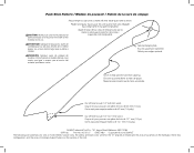
...de sorte que la main sera dégagée du protège-lame et du guide longitudinal. N273727 DWE7480 Copyright © 2013 DEWALT The following are trademarks for one or more DEWALT power tools: the yellow and black color scheme; the array of the tool. the kit box configuration; CAUTION:... plywood or softwood equal to or less than the width of push stick so hand will clear blade guard and rip fence. Orificio para colgar opcional. Cut off here to push 1/2" (12.7 mm) wood. DEWALT Industrial Tool Co., 701 Joppa Road, Baltimore, MD 21286 (APR13) Part No. Encoche pour...
...de sorte que la main sera dégagée du protège-lame et du guide longitudinal. N273727 DWE7480 Copyright © 2013 DEWALT The following are trademarks for one or more DEWALT power tools: the yellow and black color scheme; the array of the tool. the kit box configuration; CAUTION:... plywood or softwood equal to or less than the width of push stick so hand will clear blade guard and rip fence. Orificio para colgar opcional. Cut off here to push 1/2" (12.7 mm) wood. DEWALT Industrial Tool Co., 701 Joppa Road, Baltimore, MD 21286 (APR13) Part No. Encoche pour...

Parts Diagram
Page 5
Please visit www.dewaltservicenet.com for DWE7480 Type 1 Description Qty Required BEVEL POINTER 1 FRONT TRUNION 1 SCREW AND WASHER 4 CRADLE 1 SCREW 25 BLADE GUARD 1 TRUNNION BRACKET 1 SCREW AND WASHER 2 WING SCREW 4 DUST COVER 1 10 24T JOBSITE SAW BLADE 1 CLAMP WASHER 1 ARBOR NUT 1 ELEVATING SCREW 1 THRUST WASHER 2 BLOCK 1 ELEVATING SHAFT 1 WASHER 1 ELEVATING SHAFT 1 PLATE 4 MITER GAGE...
Please visit www.dewaltservicenet.com for DWE7480 Type 1 Description Qty Required BEVEL POINTER 1 FRONT TRUNION 1 SCREW AND WASHER 4 CRADLE 1 SCREW 25 BLADE GUARD 1 TRUNNION BRACKET 1 SCREW AND WASHER 2 WING SCREW 4 DUST COVER 1 10 24T JOBSITE SAW BLADE 1 CLAMP WASHER 1 ARBOR NUT 1 ELEVATING SCREW 1 THRUST WASHER 2 BLOCK 1 ELEVATING SHAFT 1 WASHER 1 ELEVATING SHAFT 1 PLATE 4 MITER GAGE...


