
Instruction Manual
Page 10
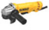
Slider switch (DWE4214) H. Side handle FIG. 1 J E J 8 DWE402, DWE402N, DWE402G K I C A DWE4214 B I . Guard release lever D. Spindle lock button K. Paddle switch G. Threaded locking flange I G D H F Type 27 Guard (4-1/2" / 115mm) C. English Minimum Gauge for Cord Sets Volts Total ...Not Recommended SAVE THESE INSTRUCTIONS FOR FUTURE USE COMPONENTS (Fig. 1) WARNING: Never modify the power tool or any part of it. Lock-off lever J. Spindle (DWE402, DWE402G) F. Lock-on button E. Damage or personal injury could result. A. Anti-lockup backing flange...
Slider switch (DWE4214) H. Side handle FIG. 1 J E J 8 DWE402, DWE402N, DWE402G K I C A DWE4214 B I . Guard release lever D. Spindle lock button K. Paddle switch G. Threaded locking flange I G D H F Type 27 Guard (4-1/2" / 115mm) C. English Minimum Gauge for Cord Sets Volts Total ...Not Recommended SAVE THESE INSTRUCTIONS FOR FUTURE USE COMPONENTS (Fig. 1) WARNING: Never modify the power tool or any part of it. Lock-off lever J. Spindle (DWE402, DWE402G) F. Lock-on button E. Damage or personal injury could result. A. Anti-lockup backing flange...

Instruction Manual
Page 14
... the switch is in power supply to full speed before putting it is A depressed. PADDLE SWITCH (FIG. 1, 4) DWE402, DWE402G CAUTION: Before connecting the tool to a power source depress and release the paddle switch (A) once [DWE402: without depressing the lock-on , the tool will start -up and during use with Type 27 wheels designed...
... the switch is in power supply to full speed before putting it is A depressed. PADDLE SWITCH (FIG. 1, 4) DWE402, DWE402G CAUTION: Before connecting the tool to a power source depress and release the paddle switch (A) once [DWE402: without depressing the lock-on , the tool will start -up and during use with Type 27 wheels designed...

Instruction Manual
Page 15
... wheel. SPINDLE LOCK BUTTON (FIG. 7) FIG. 7 The spindle lock button (D) is provided to run after the paddle switch is operating. FIG. 5 LOCK-ON BUTTON (FIG. 6) B DWE402, DWE402G The lock-on , push the lock-off lever (C) toward the front of the tool and press the forward part of the switch inward. G E 13 The...
... wheel. SPINDLE LOCK BUTTON (FIG. 7) FIG. 7 The spindle lock button (D) is provided to run after the paddle switch is operating. FIG. 5 LOCK-ON BUTTON (FIG. 6) B DWE402, DWE402G The lock-on , push the lock-off lever (C) toward the front of the tool and press the forward part of the switch inward. G E 13 The...

Instruction Manual
Page 72
the array of pyramids on the surface of lozenge-shaped humps on the handgrip; the "D" shaped air intake grill; DEWALT Industrial Tool Co., 701 East Joppa Road, Baltimore, MD 21286 (SEP14) Part No. the kit box configuration; N382909 DWE402, DWE402N, DWE402G, DWE4214 Copyright © 2014 DEWALT The following are trademarks for one or more DEWALT power tools: the yellow and black color scheme; and the array of the tool.
the array of pyramids on the surface of lozenge-shaped humps on the handgrip; the "D" shaped air intake grill; DEWALT Industrial Tool Co., 701 East Joppa Road, Baltimore, MD 21286 (SEP14) Part No. the kit box configuration; N382909 DWE402, DWE402N, DWE402G, DWE4214 Copyright © 2014 DEWALT The following are trademarks for one or more DEWALT power tools: the yellow and black color scheme; and the array of the tool.