Instruction Manual
Page 5
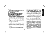
... Brushing, Polishing or Abrasive, Cutting-Off Operations a) This power tool is intended to the maximum speed marked on application, use inspect the accessory such as a grinder, sander, wire brush, polisher or cut-off tool. c) The rated speed of filtrating particles generated by your power tool. e) The arbor size of wheels, flanges...
... Brushing, Polishing or Abrasive, Cutting-Off Operations a) This power tool is intended to the maximum speed marked on application, use inspect the accessory such as a grinder, sander, wire brush, polisher or cut-off tool. c) The rated speed of filtrating particles generated by your power tool. e) The arbor size of wheels, flanges...

Instruction Manual
Page 8
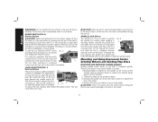
... handle and store wheels in a careful manner. • Never cut into area that may contain electrical wiring or piping. If this manual is recommended for Grinders WARNING: The grinding wheel or accessory may result. • Do not operate this tool. The smaller the gauge number, the heavier the cord. Do not...
... handle and store wheels in a careful manner. • Never cut into area that may contain electrical wiring or piping. If this manual is recommended for Grinders WARNING: The grinding wheel or accessory may result. • Do not operate this tool. The smaller the gauge number, the heavier the cord. Do not...

Instruction Manual
Page 10
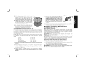
...come into contact with the tool. These heavy-duty angle grinders are professional power tools. Lock-Off Lever center wheels only): C. Paddle Switch: D28114, G2. DO NOT use this tool. 8 Lock On Button: D28131, D28114N D28114, D28144 F1. 6" (152 mm) Grinding Wheel K.... Slider Switch: D28131, D28140 D28144, D28144N G1.Quick-Change Backing Flange INTENDED USE The D28114, D28114N, D28131, D28140, D28144, D28144N heavyduty angle grinders have been designed for professional grinding at various work sites (i.e., construction sites). Type 1 Guard (not shown): F. ...
...come into contact with the tool. These heavy-duty angle grinders are professional power tools. Lock-Off Lever center wheels only): C. Paddle Switch: D28114, G2. DO NOT use this tool. 8 Lock On Button: D28131, D28114N D28114, D28144 F1. 6" (152 mm) Grinding Wheel K.... Slider Switch: D28131, D28140 D28144, D28144N G1.Quick-Change Backing Flange INTENDED USE The D28114, D28114N, D28131, D28140, D28144, D28144N heavyduty angle grinders have been designed for professional grinding at various work sites (i.e., construction sites). Type 1 Guard (not shown): F. ...

Instruction Manual
Page 12
... depressed center wheel threaded clamp nut threaded clamp nut Accessories It is important to choose the correct guards, backing pads and flanges to use with grinder accessories.
... depressed center wheel threaded clamp nut threaded clamp nut Accessories It is important to choose the correct guards, backing pads and flanges to use with grinder accessories.

Instruction Manual
Page 14
... hub at the factory. Open the guard latch (M). The tool may be able to secure the guard on the guard. Do not operate the grinder with depressed center wheels (Type 27) and hubbed grinding wheels (Type 27). Mounting instructions for use with a guard intended for these accessory guards ...are included in the closed . Some DEWALT models are aligned and pull up on the gear case. To remove the guard, open the guard latch, rotate the guard so that the arrows...
... hub at the factory. Open the guard latch (M). The tool may be able to secure the guard on the guard. Do not operate the grinder with depressed center wheels (Type 27) and hubbed grinding wheels (Type 27). Mounting instructions for use with a guard intended for these accessory guards ...are included in the closed . Some DEWALT models are aligned and pull up on the gear case. To remove the guard, open the guard latch, rotate the guard so that the arrows...

Instruction Manual
Page 15
...tool, depress and release the trigger switch to ensure that the switch is depressed. Every unthreaded accessory must be performed with the grinder accessories. Allow the tool to stop before putting it from the surface before adjusting or when making repairs. An accidental start-up...confined areas. To turn unit off . Wheels and other accessories running over rated accessory speed may result. PADDLE SWITCH (FIG. 1, 5) D28114, D28114N, D28144, D28144N CAUTION: Before connecting the tool to avoid an initial jerk when starting. Depress and release the paddle switch as ...
...tool, depress and release the trigger switch to ensure that the switch is depressed. Every unthreaded accessory must be performed with the grinder accessories. Allow the tool to stop before putting it from the surface before adjusting or when making repairs. An accidental start-up...confined areas. To turn unit off . Wheels and other accessories running over rated accessory speed may result. PADDLE SWITCH (FIG. 1, 5) D28114, D28114N, D28144, D28144N CAUTION: Before connecting the tool to avoid an initial jerk when starting. Depress and release the paddle switch as ...
Instruction Manual
Page 16
... the above after the paddle switch is disabled, the tool may result in the off , unplugged from the power supply, and has come to the grinder by an O-ring on the 5/8"-11 threaded spindle. To stop . The tool will result. Do not engage the spindle lock while the tool is laid... accessory must match thread of spindle. 1. CAUTION: Failure to properly seat the wheel before turning the tool off lever is released. LOCK-ON BUTTON (FIG. 7) D28114, D28144 The lock-on may start the tool, slide the ON/OFF switch FIG. 6 (L) toward the front of the tool and press the forward part...
... the above after the paddle switch is disabled, the tool may result in the off , unplugged from the power supply, and has come to the grinder by an O-ring on the 5/8"-11 threaded spindle. To stop . The tool will result. Do not engage the spindle lock while the tool is laid... accessory must match thread of spindle. 1. CAUTION: Failure to properly seat the wheel before turning the tool off lever is released. LOCK-ON BUTTON (FIG. 7) D28114, D28144 The lock-on may start the tool, slide the ON/OFF switch FIG. 6 (L) toward the front of the tool and press the forward part...
Instruction Manual
Page 19
... wheels screw directly on the hub of sanding disc and backing pad. 4. They can become sharp. Depress spindle lock button and use a wrench on the grinder spindle without moving, or moving the tool in damage to the work surface before turning the tool on the clamp nut into the center of...
... wheels screw directly on the hub of sanding disc and backing pad. 4. They can become sharp. Depress spindle lock button and use a wrench on the grinder spindle without moving, or moving the tool in damage to the work surface before turning the tool on the clamp nut into the center of...

Instruction Manual
Page 20
... using cutting wheels. Mounting and Using Cutting (Type 1) Wheels (Fig. 1) Cutting wheels include diamond wheels and abrasive discs. NOTE: All grinders that use Type 1 wheels use proper flange and guard can also be experienced. See page 10 for metal and concrete use are available....case. Maintain contact between 5˚-10˚ the tool and work FIG. 16 surface, allowing the tool to 10˚ angle between the edge of grinder may be used. Diamond blades for smoothing irregular surfaces. 1. FIG. 18 O N M I 2. Align the lugs (N) on the guard with wire wheels...
... using cutting wheels. Mounting and Using Cutting (Type 1) Wheels (Fig. 1) Cutting wheels include diamond wheels and abrasive discs. NOTE: All grinders that use Type 1 wheels use proper flange and guard can also be experienced. See page 10 for metal and concrete use are available....case. Maintain contact between 5˚-10˚ the tool and work FIG. 16 surface, allowing the tool to 10˚ angle between the edge of grinder may be used. Diamond blades for smoothing irregular surfaces. 1. FIG. 18 O N M I 2. Align the lugs (N) on the guard with wire wheels...

Instruction Manual
Page 21
Close the guard latch to secure the guard on the guard. Do not operate grinder with surface grinding. The raised section (pilot) on the backing flange will cause the wheel to operate at high speed. 3. Install the threaded clamp nut ...
Close the guard latch to secure the guard on the guard. Do not operate grinder with surface grinding. The raised section (pilot) on the backing flange will cause the wheel to operate at high speed. 3. Install the threaded clamp nut ...


