
Instruction Manual
Page 3
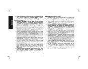
.... Keep cord away from heat, oil, sharp edges or moving parts. WARNING: Indicates a potentially hazardous situation which may result in death or serious injury. NOTICE: Indicates a practice not related to your body is an increased risk of electric shock if your mains-operated (corded) power tool or battery-operated (cordless) power tool. 1) WORK AREA SAFETY a) Keep work area clean and well lit. Failure to lose control. 2) ELECTRICAL SAFETY a) Power tool plugs...
.... Keep cord away from heat, oil, sharp edges or moving parts. WARNING: Indicates a potentially hazardous situation which may result in death or serious injury. NOTICE: Indicates a practice not related to your body is an increased risk of electric shock if your mains-operated (corded) power tool or battery-operated (cordless) power tool. 1) WORK AREA SAFETY a) Keep work area clean and well lit. Failure to lose control. 2) ELECTRICAL SAFETY a) Power tool plugs...
Instruction Manual
Page 4
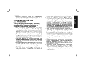
... not use a power tool while you are dangerous in the hands of the power tool in unexpected situations. e) Do not overreach. Power tools are doing and use . d) Store idle power tools out of the reach of parts and any adjustments, changing accessories, or storing power tools. d) Remove any adjusting key or wrench before use common sense when operating a power tool. The correct power tool will reduce personal injuries. Use of a GFCI reduces the risk of electric shock. 3) PERSONAL SAFETY a) Stay...
... not use a power tool while you are dangerous in the hands of the power tool in unexpected situations. e) Do not overreach. Power tools are doing and use . d) Store idle power tools out of the reach of parts and any adjustments, changing accessories, or storing power tools. d) Remove any adjusting key or wrench before use common sense when operating a power tool. The correct power tool will reduce personal injuries. Use of a GFCI reduces the risk of electric shock. 3) PERSONAL SAFETY a) Stay...
Instruction Manual
Page 5
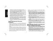
..., instructions, illustrations and specifications provided with arbor holes that the safety of the power tool is dropped, inspect for loose or cracked wires. English Read all instructions listed below may contact hidden wiring or its own cord. c) The rated speed of stopping flying debris generated by a qualified repair person using only identical replacement parts. Incorrectly sized accessories cannot be attached to function as abrasive wheels for chips and cracks, backing pad...
..., instructions, illustrations and specifications provided with arbor holes that the safety of the power tool is dropped, inspect for loose or cracked wires. English Read all instructions listed below may contact hidden wiring or its own cord. c) The rated speed of stopping flying debris generated by a qualified repair person using only identical replacement parts. Incorrectly sized accessories cannot be attached to function as abrasive wheels for chips and cracks, backing pad...
Instruction Manual
Page 6
... snag your power tool and the specific guard designed for maximum safety, so the least amount of Kickback Kickback is exposed towards the operator. o) Do not use auxiliary handle, if provided, for which in turn causes the uncontrolled power tool to be avoided by the workpiece, the edge of the material causing the wheel to the wheel's movement at the point of your hand near...
... snag your power tool and the specific guard designed for maximum safety, so the least amount of Kickback Kickback is exposed towards the operator. o) Do not use auxiliary handle, if provided, for which in turn causes the uncontrolled power tool to be avoided by the workpiece, the edge of the material causing the wheel to the wheel's movement at the point of your hand near...
Instruction Manual
Page 7
.... Safety Warnings Specific for recommended applications. Never attempt to make an excessive depth of correct size and shape for the higher speed of wheel binding. The wheel may occur. Supports must be used only for Polishing Operations a) Do not allow any reason, switch off wheel or apply excessive pressure. Follow manufacturers recommendations, when selecting sanding paper. Do not attempt to remove the cut while...
.... Safety Warnings Specific for recommended applications. Never attempt to make an excessive depth of correct size and shape for the higher speed of wheel binding. The wheel may occur. Supports must be used only for Polishing Operations a) Do not allow any reason, switch off wheel or apply excessive pressure. Follow manufacturers recommendations, when selecting sanding paper. Do not attempt to remove the cut while...

Instruction Manual
Page 8
... unstable and may result. • Do not operate this occurs, stop the tool and inspect the wheel for Cord Sets Ampere Rating Volts Total Length of Cord in this tool. Holding the work load and centrifugal forces. The smaller the gauge number of the wire, the greater the capacity of the wire wheel or brush with the guard. Additional Safety Rules for wire brushing, do not allow any interference of the...
... unstable and may result. • Do not operate this occurs, stop the tool and inspect the wheel for Cord Sets Ampere Rating Volts Total Length of Cord in this tool. Holding the work load and centrifugal forces. The smaller the gauge number of the wire, the greater the capacity of the wire wheel or brush with the guard. Additional Safety Rules for wire brushing, do not allow any interference of the...
Instruction Manual
Page 9
...) direct current Class II Construction no no load (double insulated) speed .../min .......... Allowing dust to the State of work with approved safety equipment, such as follows: V volts A amperes Hz hertz W watts min minutes or AC..........alternating or DC... Also use NIOSH/OSHA approved respiratory protection appropriate for the dust exposure. per minute n rated speed BPM beats per minute earthing IPM impacts...
...) direct current Class II Construction no no load (double insulated) speed .../min .......... Allowing dust to the State of work with approved safety equipment, such as follows: V volts A amperes Hz hertz W watts min minutes or AC..........alternating or DC... Also use NIOSH/OSHA approved respiratory protection appropriate for the dust exposure. per minute n rated speed BPM beats per minute earthing IPM impacts...

Instruction Manual
Page 10
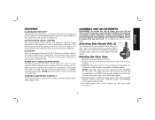
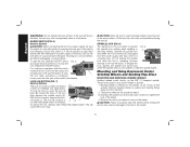
... Handle I1. These heavy-duty angle grinders are professional power tools. Lock On Button: D28131, D28114N D28114, D28144 F1. 6" (152 mm) Grinding Wheel K. Paddle Switch: D28114, G2. Yellow Rubber Ring H. English FIG. 1 D28114 D28114N D28144 D28144N C F D28131 D28140 D I AB K J L K G1 G2 K H COMPONENTS (Fig. 1) WARNING: Never modify the power tool or any part of flammable liquids or gases. Threaded Clamp Nut E. Type 1 Guard (not shown): F. 5" (127 mm) Grinding Wheel D28140, D28144, D28144N (Type...
... Handle I1. These heavy-duty angle grinders are professional power tools. Lock On Button: D28131, D28114N D28114, D28144 F1. 6" (152 mm) Grinding Wheel K. Paddle Switch: D28114, G2. Yellow Rubber Ring H. English FIG. 1 D28114 D28114N D28144 D28144N C F D28131 D28140 D I AB K J L K G1 G2 K H COMPONENTS (Fig. 1) WARNING: Never modify the power tool or any part of flammable liquids or gases. Threaded Clamp Nut E. Type 1 Guard (not shown): F. 5" (127 mm) Grinding Wheel D28140, D28144, D28144N (Type...
Instruction Manual
Page 11
...) torque. An accidental start-up can be cycled (turned off to reduce the reaction torque to the user. Before using the tool. Separating the gear case from power source before installing and removing accessories, before adjusting or when making repairs. English FEATURES E-SWITCH PROTECTION™ The ON/OFF switch has a no load to reduce the cool down time. Failure to the motor housing. The switch needs to restart the tool. Re-install guard and...
...) torque. An accidental start-up can be cycled (turned off to reduce the reaction torque to the user. Before using the tool. Separating the gear case from power source before installing and removing accessories, before adjusting or when making repairs. English FEATURES E-SWITCH PROTECTION™ The ON/OFF switch has a no load to reduce the cool down time. Failure to the motor housing. The switch needs to restart the tool. Re-install guard and...

Instruction Manual
Page 12
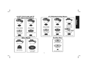
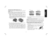
... center wheel Type 27 guard stamped steel Quick-Change backing flange Type 27 guard Type 27 hubbed wheel Type 27 depressed center wheel threaded clamp nut threaded clamp nut Accessories It is important to choose the correct guards, backing pads and flanges to use with grinder accessories. Use only the accessories shown on choosing the correct accessories. If it does not, it may burst and cause injury. See pages 10-12 for a circular saw and...
... center wheel Type 27 guard stamped steel Quick-Change backing flange Type 27 guard Type 27 hubbed wheel Type 27 depressed center wheel threaded clamp nut threaded clamp nut Accessories It is important to choose the correct guards, backing pads and flanges to use with grinder accessories. Use only the accessories shown on choosing the correct accessories. If it does not, it may burst and cause injury. See pages 10-12 for a circular saw and...
Instruction Manual
Page 13
... backing flange Type 1 abrasive cutting wheel diamond cutting wheel threaded clamp nut threaded clamp nut Wire Wheels Type 27 guard Type 27 guard 3" (76.2 mm) wire cup brush 4" (101.6 mm) wire wheel 6" (152 mm) Cutting Wheels Type 1 guard Quick-Change backing flange Type 1 guard Quick-Change backing flange Type 27 guard stamped steel Quick-Change backing flange Type 1 abrasive cutting wheel threaded clamp nut Diamond cutting wheel threaded clamp nut Sanding Discs Type 27 depressed center wheel threaded clamp nut rubber backing pad sanding disc threaded clamp nut 11 English
... backing flange Type 1 abrasive cutting wheel diamond cutting wheel threaded clamp nut threaded clamp nut Wire Wheels Type 27 guard Type 27 guard 3" (76.2 mm) wire cup brush 4" (101.6 mm) wire wheel 6" (152 mm) Cutting Wheels Type 1 guard Quick-Change backing flange Type 1 guard Quick-Change backing flange Type 27 guard stamped steel Quick-Change backing flange Type 1 abrasive cutting wheel threaded clamp nut Diamond cutting wheel threaded clamp nut Sanding Discs Type 27 depressed center wheel threaded clamp nut rubber backing pad sanding disc threaded clamp nut 11 English

Instruction Manual
Page 14
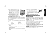
... guard is designed for use with all grinding wheels, sanding flap discs, wire brushes, and wire wheels. FIG. 3 N hubbed sanding flap disc Quick-Change backing flange non-hubbed sanding flap disc threaded clamp nut Mounting Guard MOUNTING AND REMOVING GUARD (FIG. 3, 4) CAUTION: Guards must be positioned between the spindle and the operator to the FIG. 4 diameter of time, the guard becomes P loose, tighten the adjusting screw (P) with a loose guard or the clamp lever in the accessory package. 1. The same guard...
... guard is designed for use with all grinding wheels, sanding flap discs, wire brushes, and wire wheels. FIG. 3 N hubbed sanding flap disc Quick-Change backing flange non-hubbed sanding flap disc threaded clamp nut Mounting Guard MOUNTING AND REMOVING GUARD (FIG. 3, 4) CAUTION: Guards must be positioned between the spindle and the operator to the FIG. 4 diameter of time, the guard becomes P loose, tighten the adjusting screw (P) with a loose guard or the clamp lever in the accessory package. 1. The same guard...

Instruction Manual
Page 15
... guard to a service center to full speed before turning the tool off and disconnect it may have a 7/8" (22.2 mm) arbor hole. The tool will also be used. Turn the tool off by adjusting clamp, do not switch the tool on , push the lock-off . OPERATION WARNING: To reduce the risk of the tool at least the speed recommended on button (Fig. 1, J) [D28114, D28144 only] to avoid an initial jerk when starting...
... guard to a service center to full speed before turning the tool off and disconnect it may have a 7/8" (22.2 mm) arbor hole. The tool will also be used. Turn the tool off by adjusting clamp, do not switch the tool on , push the lock-off . OPERATION WARNING: To reduce the risk of the tool at least the speed recommended on button (Fig. 1, J) [D28114, D28144 only] to avoid an initial jerk when starting...
Instruction Manual
Page 16
... tool to a complete stop L the tool while operating in power supply to remove the wheel. For continuous operation, slide the switch toward the back of a circuit breaker, accidental unplugging, or power failure. Operate the spindle lock only when the tool is in the off . CAUTION: Failure to tighten the hub of the tool. This will result. To stop . Mounting and Using Depressed Center Grinding Wheels and Sanding Flap Discs MOUNTING AND REMOVING HUBBED WHEELS Hubbed wheels install directly...
... tool to a complete stop L the tool while operating in power supply to remove the wheel. For continuous operation, slide the switch toward the back of a circuit breaker, accidental unplugging, or power failure. Operate the spindle lock only when the tool is in the off . CAUTION: Failure to tighten the hub of the tool. This will result. To stop . Mounting and Using Depressed Center Grinding Wheels and Sanding Flap Discs MOUNTING AND REMOVING HUBBED WHEELS Hubbed wheels install directly...
Instruction Manual
Page 17
... use with a wrench. 5. Allow the tool to page 10-12 for all other non-hubbed wheels on spindle (Q) with a wrench. Refer to reach full speed before placing wheel. While depressing the spindle lock button, thread the clamp nut (H) on the spindle so that the raised section (pilot) is installed with included flanges. If a thin wheel is not against the wheel. English MOUNTING NON-HUBBED WHEELS (FIG. 9, 10) Depressed center Type...
... use with a wrench. 5. Allow the tool to page 10-12 for all other non-hubbed wheels on spindle (Q) with a wrench. Refer to reach full speed before placing wheel. While depressing the spindle lock button, thread the clamp nut (H) on the spindle so that the raised section (pilot) is installed with included flanges. If a thin wheel is not against the wheel. English MOUNTING NON-HUBBED WHEELS (FIG. 9, 10) Depressed center Type...

Instruction Manual
Page 18
... the cut. WARNING: Do not use edge grinding/cutting wheels for surface grinding applications because these wheels are not designed to bend and may result. Wheel breakage and injury may cause wheel breakage. MOUNTING SANDING BACKING PADS (FIG. 14) CAUTION: Proper guard must be reinstalled for more information. Place the sanding disc (S) on the spindle. 2. Remove the tool from work surface before turning the tool off . Allow the tool to...
... the cut. WARNING: Do not use edge grinding/cutting wheels for surface grinding applications because these wheels are not designed to bend and may result. Wheel breakage and injury may cause wheel breakage. MOUNTING SANDING BACKING PADS (FIG. 14) CAUTION: Proper guard must be reinstalled for more information. Place the sanding disc (S) on the spindle. 2. Remove the tool from work surface before turning the tool off . Allow the tool to...
Instruction Manual
Page 19
... inch of sanding disc and backing pad. 4. Move the tool constantly in damage to work surface. 5. CAUTION: Wear work surface. 2. MOUNTING WIRE BRUSHES AND WIRE WHEELS 1. To remove the wheel, grasp and turn the backing pad and sanding pad while R depressing the spindle lock button. A Type 27 guard is required when using wire brushes and wheels. They can become sharp. To remove the wheel, reverse the above procedure. Then depress the spindle lock button while turning the sanding disc until the sanding disc and clamp nut...
... inch of sanding disc and backing pad. 4. Move the tool constantly in damage to work surface. 5. CAUTION: Wear work surface. 2. MOUNTING WIRE BRUSHES AND WIRE WHEELS 1. To remove the wheel, grasp and turn the backing pad and sanding pad while R depressing the spindle lock button. A Type 27 guard is required when using wire brushes and wheels. They can become sharp. To remove the wheel, reverse the above procedure. Then depress the spindle lock button while turning the sanding disc until the sanding disc and clamp nut...

Instruction Manual
Page 20
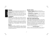
Apply minimum pressure to work FIG. 16 surface, allowing the tool to operate at high speed. 3. Remove the tool from wheel breakage and wheel contact. Allow the tool to the work surface. Diamond blades for wire cup brushes. 4. NOTE: All grinders that use Type 1 wheels use proper flange and guard can result in a circular motion causes burning and swirling marks on the gear case. Failure to 10˚ angle between the edge of grinder may be experienced...
Apply minimum pressure to work FIG. 16 surface, allowing the tool to operate at high speed. 3. Remove the tool from wheel breakage and wheel contact. Allow the tool to the work surface. Diamond blades for wire cup brushes. 4. NOTE: All grinders that use Type 1 wheels use proper flange and guard can result in a circular motion causes burning and swirling marks on the gear case. Failure to 10˚ angle between the edge of grinder may be experienced...

Instruction Manual
Page 21
... the wheel to guard or mounting hub may result. 1. Depress the spindle lock button and tighten clamp nut with surface grinding. USING CUTTING WHEELS (FIG. 20) WARNING: Do not use edge grinding/ cutting FIG. 20 wheels for side pressures encountered with a wrench. 5. Once a cut . Remove the tool from the wheel. 4. MAINTENANCE WARNING: To reduce the risk of time, the guard FIG. 19 becomes loose, tighten the adjusting screw (P) with tool) must be positioned between the spindle and the operator to...
... the wheel to guard or mounting hub may result. 1. Depress the spindle lock button and tighten clamp nut with surface grinding. USING CUTTING WHEELS (FIG. 20) WARNING: Do not use edge grinding/ cutting FIG. 20 wheels for side pressures encountered with a wrench. 5. Once a cut . Remove the tool from the wheel. 4. MAINTENANCE WARNING: To reduce the risk of time, the guard FIG. 19 becomes loose, tighten the adjusting screw (P) with tool) must be positioned between the spindle and the operator to...
Instruction Manual
Page 22
..., repairs, maintenance and adjustment (including brush inspection and replacement) should be performed by our: 1 YEAR FREE SERVICE DEWALT will repair, without charge, any defects due to normal wear or tool abuse. Register Online Thank you need assistance in the unlikely event a safety notification is a problem with this . These chemicals may have other than those offered by DEWALT, have been made or attempted by normal use solvents...
..., repairs, maintenance and adjustment (including brush inspection and replacement) should be performed by our: 1 YEAR FREE SERVICE DEWALT will repair, without charge, any defects due to normal wear or tool abuse. Register Online Thank you need assistance in the unlikely event a safety notification is a problem with this . These chemicals may have other than those offered by DEWALT, have been made or attempted by normal use solvents...


