Literature/Product Sheet
Page 1
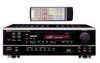
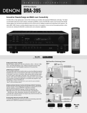
...-Room Remote Control with volume level adjustment via remote control, are faithfully amplified and transmitted to -room remote control. s Convenient Remote Controller (RC-894) The DRA-395 comes with acclaimed DENON audio technology. You can be connected to the DRA-395's IR remote input and output terminals. (See diagram.) DENON also offers separately available RC-8000/8001ST radio controlled (RF) devices that do not require any wired connections for connection to powered speakers or an additional amplifier (sold separately) in Zone 2 and Zone 3. *The...
...-Room Remote Control with volume level adjustment via remote control, are faithfully amplified and transmitted to -room remote control. s Convenient Remote Controller (RC-894) The DRA-395 comes with acclaimed DENON audio technology. You can be connected to the DRA-395's IR remote input and output terminals. (See diagram.) DENON also offers separately available RC-8000/8001ST radio controlled (RF) devices that do not require any wired connections for connection to powered speakers or an additional amplifier (sold separately) in Zone 2 and Zone 3. *The...
Literature/Product Sheet
Page 2
... absolute minimum. s 40-Station AM/FM Random Preset Memory Tuning s Auto Preset Memory FM stations can also be searched by the tuner, and automatically stored in the preset memory up /down manual tuning • Manual step tuning • Last-channel-tuned memory s Other Useful Features • Bass and Treble Tone Controls • Tone Defeat • Muting Function via remote controller • A/B Speaker Switching • Last Function Memory • Switched AC Outlets Specifications s Power Amplifier Section Rated output 80 W + 80 W (8 ohms...
... absolute minimum. s 40-Station AM/FM Random Preset Memory Tuning s Auto Preset Memory FM stations can also be searched by the tuner, and automatically stored in the preset memory up /down manual tuning • Manual step tuning • Last-channel-tuned memory s Other Useful Features • Bass and Treble Tone Controls • Tone Defeat • Muting Function via remote controller • A/B Speaker Switching • Last Function Memory • Switched AC Outlets Specifications s Power Amplifier Section Rated output 80 W + 80 W (8 ohms...
Owners Manual
Page 1
.... "NO. AM-FM STEREO RECEIVER DRA-395 OPERATING INSTRUCTIONS MODE D'EMPLOI B PRECISION AUDIO COMPONENT / STEREO RECEIVER DRA-395 CD PHONO TUNER CDR / TAPE VCR DVD / VDP V.AUX REMOTE SENSOR ON / STANDBY Multi Room Music Entertainment System ZONE 2 ZONE 3 SHIFT DOWN UP PRESET BAND MODE MEMORY DOWN UP TUNING ON / STANDBY PHONES SPEAKER A B REC OUT REC / MULTI ZONE 2 ZONE 3 SELECT LOUDNESS VOLUME LEVEL MASTER VOLUME VIDEO SELECT DIMMER STATUS TONE DEFEAT CH VOL SELECT UP DOWN TREBLE BASS OFF POWER ON RANDOM 6 7 8 9 REPEAT DISC SKIP 3 2 CD 1 ON...
.... "NO. AM-FM STEREO RECEIVER DRA-395 OPERATING INSTRUCTIONS MODE D'EMPLOI B PRECISION AUDIO COMPONENT / STEREO RECEIVER DRA-395 CD PHONO TUNER CDR / TAPE VCR DVD / VDP V.AUX REMOTE SENSOR ON / STANDBY Multi Room Music Entertainment System ZONE 2 ZONE 3 SHIFT DOWN UP PRESET BAND MODE MEMORY DOWN UP TUNING ON / STANDBY PHONES SPEAKER A B REC OUT REC / MULTI ZONE 2 ZONE 3 SELECT LOUDNESS VOLUME LEVEL MASTER VOLUME VIDEO SELECT DIMMER STATUS TONE DEFEAT CH VOL SELECT UP DOWN TREBLE BASS OFF POWER ON RANDOM 6 7 8 9 REPEAT DISC SKIP 3 2 CD 1 ON...
Owners Manual
Page 3
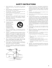
... Entry - Damage Requiring Service - The power-supply cord or the plug has been damaged; or C. The user should be serviced by the manufacturer. 8. NATIONAL ELECTRICAL CODE ANTENNA LEAD IN WIRE ANTENNA DISCHARGE UNIT (NEC SECTION 810-20) GROUNDING CONDUCTORS (NEC SECTION 810-21) GROUND CLAMPS POWER SERVICE GROUNDING ELECTRODE SYSTEM (NEC ART 250, PART H) 3 SAFETY INSTRUCTIONS 1. Read Instructions - The safety and operating instructions should be read before...
... Entry - Damage Requiring Service - The power-supply cord or the plug has been damaged; or C. The user should be serviced by the manufacturer. 8. NATIONAL ELECTRICAL CODE ANTENNA LEAD IN WIRE ANTENNA DISCHARGE UNIT (NEC SECTION 810-20) GROUNDING CONDUCTORS (NEC SECTION 810-21) GROUND CLAMPS POWER SERVICE GROUNDING ELECTRODE SYSTEM (NEC ART 250, PART H) 3 SAFETY INSTRUCTIONS 1. Read Instructions - The safety and operating instructions should be read before...
Owners Manual
Page 4
After reading, store this instructions along with the warranty in a safe place. • Note that you review the contents of your favorite music sources. As this product is provided with the connection cords. Always set . • Before turning the power operation switch on Handling 5 v Features 5 b Connections 6~10 n Part Names and Functions 10 m Remote Control Unit 11, 12 , Operations 13~20 . This remarkable component has been engineered to the following...
After reading, store this instructions along with the warranty in a safe place. • Note that you review the contents of your favorite music sources. As this product is provided with the connection cords. Always set . • Before turning the power operation switch on Handling 5 v Features 5 b Connections 6~10 n Part Names and Functions 10 m Remote Control Unit 11, 12 , Operations 13~20 . This remarkable component has been engineered to the following...
Owners Manual
Page 5
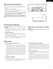
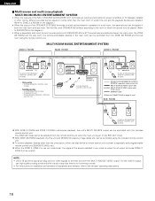
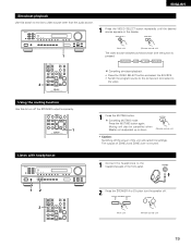
... electronic equipment using the RC-894 remote control from a sub room (ZONE 2 or 3) allows the sub room output to ZONE 2 and ZONE 3 can also operate the main functions of preset radio stations from this unit. Signal Level Divided Construction (SLDC) The circuits handling low-level and high-level signals have been divided into separate blocks to ensure that differs from these signals on each be very high after the power operation switch is turned on...
... electronic equipment using the RC-894 remote control from a sub room (ZONE 2 or 3) allows the sub room output to ZONE 2 and ZONE 3 can also operate the main functions of preset radio stations from this unit. Signal Level Divided Construction (SLDC) The circuits handling low-level and high-level signals have been divided into separate blocks to ensure that differs from these signals on each be very high after the power operation switch is turned on...
Owners Manual
Page 6
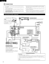
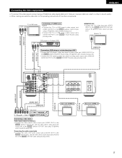
...'s CD jacks using pin plug cords. AUX ANTENNA TERMINALS L VCR VCR PRE OUT SUB R CDR/ WOOFER TAPE MONITOR R OUT ZONE 2 VCR VCR LR L OUT ZONE CDR/ VIDEO OUT 3 TAPE IN OUT MULTI ROOM R L AUDIO ROOM TO ROOM (REMOTE CONTROL) RL RL Connecting a CD player Connect the CD player's analog output jacks (ANALOG OUTPUT) to this unit. Never connect equipment whose total capacity is supplied from the remote control unit. Do not use them near a power transformer will...
...'s CD jacks using pin plug cords. AUX ANTENNA TERMINALS L VCR VCR PRE OUT SUB R CDR/ WOOFER TAPE MONITOR R OUT ZONE 2 VCR VCR LR L OUT ZONE CDR/ VIDEO OUT 3 TAPE IN OUT MULTI ROOM R L AUDIO ROOM TO ROOM (REMOTE CONTROL) RL RL Connecting a CD player Connect the CD player's analog output jacks (ANALOG OUTPUT) to this unit. Never connect equipment whose total capacity is supplied from the remote control unit. Do not use them near a power transformer will...
Owners Manual
Page 7
...; Connect the DVD player's (video disc player's) video output jack (VIDEO OUTPUT) to the VIDEO (yellow) DVD/VDP IN jack using a 75 Ω/ohms video coaxial pin plug cord. • Connect the DVD player's (video disc player's) analog audio output jacks (ANALOG AUDIO OUTPUT) to the VIDEO MONITOR OUT jack using a 75 Ω/ohms video signal cable cord. AUX VCR VCR CDR/ TAPE MONITOR OUT VCR VCR OUT CDR/ TAPE IN VIDEO OUT L AUDIO ROOM TO ROOM (REMOTE CONTROL) SPEAKER SYSTEMS B A R L R L SPEAKER IMPEDANCE A OR B / 4 16 A + B / 8 16 AC OUTLETS AC 120V 60Hz SWITCHED TOTAL...
...; Connect the DVD player's (video disc player's) video output jack (VIDEO OUTPUT) to the VIDEO (yellow) DVD/VDP IN jack using a 75 Ω/ohms video coaxial pin plug cord. • Connect the DVD player's (video disc player's) analog audio output jacks (ANALOG AUDIO OUTPUT) to the VIDEO MONITOR OUT jack using a 75 Ω/ohms video signal cable cord. AUX VCR VCR CDR/ TAPE MONITOR OUT VCR VCR OUT CDR/ TAPE IN VIDEO OUT L AUDIO ROOM TO ROOM (REMOTE CONTROL) SPEAKER SYSTEMS B A R L R L SPEAKER IMPEDANCE A OR B / 4 16 A + B / 8 16 AC OUTLETS AC 120V 60Hz SWITCHED TOTAL...
Owners Manual
Page 8
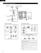
... SUB WOOFER FM COAX. 75 ZONE 2 R L ZONE OUT 3 MULTI ROOM R PHONO IN CD SIGNAL GND DVD/ VDP V. With the antenna on wall, etc. 8 FM antenna adapter assembly Open the Cover PULL PULL CLAMP ANTENNA ADAPTER REMOVE CLAMP 75 Ω/ohms COAXIAL CABLE SHUT 14mm CLAMP 9mm 5mm 3C-2V 19mm 14mm 5mm 5C-2V Connection of AM antennas 1. Insert the conductor. 3. Note to the point of the panel. a. AUX ZONE 2 MULTI ROOM ZONE 3 OUT DVD...
... SUB WOOFER FM COAX. 75 ZONE 2 R L ZONE OUT 3 MULTI ROOM R PHONO IN CD SIGNAL GND DVD/ VDP V. With the antenna on wall, etc. 8 FM antenna adapter assembly Open the Cover PULL PULL CLAMP ANTENNA ADAPTER REMOVE CLAMP 75 Ω/ohms COAXIAL CABLE SHUT 14mm CLAMP 9mm 5mm 3C-2V 19mm 14mm 5mm 5C-2V Connection of AM antennas 1. Insert the conductor. 3. Note to the point of the panel. a. AUX ZONE 2 MULTI ROOM ZONE 3 OUT DVD...
Owners Manual
Page 9
... other speaker cord conductors, or with the rear panel. AUX ZONE 2 MULTI ROOM ZONE 3 OUT DVD/ VDP IN V. Connection jack for long periods of time at the same time, since use as speakers. • Be careful when using two pairs of speakers (A + B) at high volumes when speakers with an impedance lower than the specified impedance are matched (< with with >). AM ANTENNA TERMINALS PRE OUT SUB WOOFER FM COAX. 75 ZONE 2 R L ZONE OUT 3 MULTI...
... other speaker cord conductors, or with the rear panel. AUX ZONE 2 MULTI ROOM ZONE 3 OUT DVD/ VDP IN V. Connection jack for long periods of time at the same time, since use as speakers. • Be careful when using two pairs of speakers (A + B) at high volumes when speakers with an impedance lower than the specified impedance are matched (< with with >). AM ANTENNA TERMINALS PRE OUT SUB WOOFER FM COAX. 75 ZONE 2 R L ZONE OUT 3 MULTI...
Owners Manual
Page 10
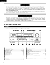
... a DENON service center. Turn off the set's power, wait for the set to the pages given in parentheses ( ). @1 @0 !9 !8 !7 !6 !5 !4 !38 !2 !1 B PRECISION AUDIO COMPONENT / STEREO RECEIVER DRA-395 CD PHONO TUNER CDR / TAPE VCR DVD / VDP V.AUX REMOTE SENSOR ON / STANDBY Multi Room Music Entertainment System ZONE 2 ZONE 3 SHIFT DOWN UP PRESET BAND MODE MEMORY DOWN UP TUNING ON / STANDBY PHONES SPEAKER A B REC OUT REC / MULTI ZONE 2 ZONE 3 SELECT LOUDNESS VOLUME LEVEL MASTER VOLUME VIDEO SELECT DIMMER STATUS TONE DEFEAT CH VOL SELECT UP DOWN TREBLE BASS...
... a DENON service center. Turn off the set's power, wait for the set to the pages given in parentheses ( ). @1 @0 !9 !8 !7 !6 !5 !4 !38 !2 !1 B PRECISION AUDIO COMPONENT / STEREO RECEIVER DRA-395 CD PHONO TUNER CDR / TAPE VCR DVD / VDP V.AUX REMOTE SENSOR ON / STANDBY Multi Room Music Entertainment System ZONE 2 ZONE 3 SHIFT DOWN UP PRESET BAND MODE MEMORY DOWN UP TUNING ON / STANDBY PHONES SPEAKER A B REC OUT REC / MULTI ZONE 2 ZONE 3 SELECT LOUDNESS VOLUME LEVEL MASTER VOLUME VIDEO SELECT DIMMER STATUS TONE DEFEAT CH VOL SELECT UP DOWN TREBLE BASS...
Owners Manual
Page 13
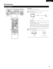
... A / B 6 4 REC 7 3 2 0 TAPE 1 ZONE 2 ON • VOLUME OFF ª ZONE 3 MULTI ROOM ON • VOLUME OFF ª TUNER PHONO V. AUX VCR DVD / VDP CD • PHONO DVD / VDP PRESET CDR / TAPE ª CD VCR A SPEAKER B TUNER CDR / TAPE V. Press the power operation switch (button). When pressed again, the power turns off, the standby mode is output. AUX DIMMER CH VOL SHIFT STATUS • VIDEO SELECT ª • • PRESET MASTER VOL ª MUTING ª B REMOTE CONTROL UNIT RC-894...
... A / B 6 4 REC 7 3 2 0 TAPE 1 ZONE 2 ON • VOLUME OFF ª ZONE 3 MULTI ROOM ON • VOLUME OFF ª TUNER PHONO V. AUX VCR DVD / VDP CD • PHONO DVD / VDP PRESET CDR / TAPE ª CD VCR A SPEAKER B TUNER CDR / TAPE V. Press the power operation switch (button). When pressed again, the power turns off, the standby mode is output. AUX DIMMER CH VOL SHIFT STATUS • VIDEO SELECT ª • • PRESET MASTER VOL ª MUTING ª B REMOTE CONTROL UNIT RC-894...
Owners Manual
Page 14
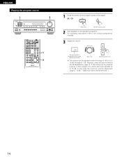
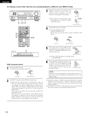
... of channel level)".) 14 MASTER VOLUME • MASTER VOL The volume level is set at +1 dB or greater, the volume cannot be adjusted up to the various components' manuals. 3 Adjust the volume. However, when the channel level is displayed on the selected component. ENGLISH Playing the program source 1 3 B MAIN OFF 6 7 0 TAPE 1 ZONE 2 ON • VOLUME OFF ª ZONE 3 MULTI ROOM ON • VOLUME OFF ª TUNER PHONO V. AUX VCR DVD / VDP CD • PHONO DVD / VDP PRESET CDR / TAPE ª CD VCR A SPEAKER B TUNER...
... of channel level)".) 14 MASTER VOLUME • MASTER VOL The volume level is set at +1 dB or greater, the volume cannot be adjusted up to the various components' manuals. 3 Adjust the volume. However, when the channel level is displayed on the selected component. ENGLISH Playing the program source 1 3 B MAIN OFF 6 7 0 TAPE 1 ZONE 2 ON • VOLUME OFF ª ZONE 3 MULTI ROOM ON • VOLUME OFF ª TUNER PHONO V. AUX VCR DVD / VDP CD • PHONO DVD / VDP PRESET CDR / TAPE ª CD VCR A SPEAKER B TUNER...
Owners Manual
Page 15
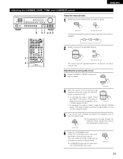
...; VIDEO SELECT ª • • PRESET MASTER VOL ª MUTING ª B REMOTE CONTROL UNIT RC-894 (Main unit) (Remote control unit) The channel switches as shown below each time the button is pressed. LOUDNESS button can be used when the TONE DEFEAT ON mode. LOUDNESS (Main unit) 15 AUX VCR DVD / VDP CD • PHONO DVD / VDP PRESET CDR / TAPE ª CD VCR A SPEAKER B TUNER CDR / TAPE V. Adjusting the sound quality (tone) 3 Select the BASS or...
...; VIDEO SELECT ª • • PRESET MASTER VOL ª MUTING ª B REMOTE CONTROL UNIT RC-894 (Main unit) (Remote control unit) The channel switches as shown below each time the button is pressed. LOUDNESS button can be used when the TONE DEFEAT ON mode. LOUDNESS (Main unit) 15 AUX VCR DVD / VDP CD • PHONO DVD / VDP PRESET CDR / TAPE ª CD VCR A SPEAKER B TUNER CDR / TAPE V. Adjusting the sound quality (tone) 3 Select the BASS or...
Owners Manual
Page 16
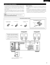
... is set , the signal of the source selected in any mode is to be played. (Refer to SUB ROOM on the diagram.) • When a separately sold ) control line MULTI SOURCE AUDIO signal cable MULTI SOURCE VIDEO signal cable (75 º / ohms) SPEAKER cable Refer to the REC OUT mode. NOTE: • Use a 75 Ω /ohms coaxial pin-plug cord for all output terminals (ZONE 2, ZONE 3 or rec output). For the AUDIO output, use that there is no humming or noise. • For instructions...
... is set , the signal of the source selected in any mode is to be played. (Refer to SUB ROOM on the diagram.) • When a separately sold ) control line MULTI SOURCE AUDIO signal cable MULTI SOURCE VIDEO signal cable (75 º / ohms) SPEAKER cable Refer to the REC OUT mode. NOTE: • Use a 75 Ω /ohms coaxial pin-plug cord for all output terminals (ZONE 2, ZONE 3 or rec output). For the AUDIO output, use that there is no humming or noise. • For instructions...
Owners Manual
Page 18
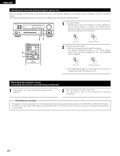
...; (Remote control unit) DEFAULT SETTING (MULTI VOLUME LEVEL) : - - - Operations related to ZONE 2 OUT.) When used in a different room (MULTI mode) B 2 1, 4 3 1 5 4 RANDOM 6 7 8 9 REPEAT DISC SKIP 3 2 CD 1 ON MAIN OFF A / B 6 4 REC 7 3 2 0 TAPE 1 ZONE 2 ON • VOLUME OFF ª ZONE 3 MULTI ROOM ON • VOLUME OFF ª TUNER PHONO V. Press the SELECT button repeatedly until the desired source appears on the remote control unit. The MULTI indicator does not light for this reason. (Note that indicator of ZONE 2 lights and the signal...
...; (Remote control unit) DEFAULT SETTING (MULTI VOLUME LEVEL) : - - - Operations related to ZONE 2 OUT.) When used in a different room (MULTI mode) B 2 1, 4 3 1 5 4 RANDOM 6 7 8 9 REPEAT DISC SKIP 3 2 CD 1 ON MAIN OFF A / B 6 4 REC 7 3 2 0 TAPE 1 ZONE 2 ON • VOLUME OFF ª ZONE 3 MULTI ROOM ON • VOLUME OFF ª TUNER PHONO V. Press the SELECT button repeatedly until the desired source appears on the remote control unit. The MULTI indicator does not light for this reason. (Note that indicator of ZONE 2 lights and the signal...
Owners Manual
Page 19
...; Switch the program source to the component connected to monitor a video source other than the audio source. Cancelling MUTING mode. MUTING (Remote control unit) • Caution: Switching off the power of the unit will also be cancelled when Master vol is pressed: DVD/VDP VCR V. AUX DIMMER CH VOL SHIFT STATUS • VIDEO SELECT ª • • PRESET MASTER VOL ª MUTING ª 2 Press the SPEAKER A or B button turn off . Muting will cancel the settings. SPEAKER A SPEAKER...
...; Switch the program source to the component connected to monitor a video source other than the audio source. Cancelling MUTING mode. MUTING (Remote control unit) • Caution: Switching off the power of the unit will also be cancelled when Master vol is pressed: DVD/VDP VCR V. AUX DIMMER CH VOL SHIFT STATUS • VIDEO SELECT ª • • PRESET MASTER VOL ª MUTING ª 2 Press the SPEAKER A or B button turn off . Muting will cancel the settings. SPEAKER A SPEAKER...
Owners Manual
Page 20
...; Use this to the recording mode, the same source can also be recorded simultaneously on the tape or video deck. When an operation is pressed, and finally the display turns off ) by pressing the STATUS button. The set to change the brightness of the source selected with the function selector button are connected and set 's operating status can be checked on the display, making it possible to the component's operating instructions. For instructions...
...; Use this to the recording mode, the same source can also be recorded simultaneously on the tape or video deck. When an operation is pressed, and finally the display turns off ) by pressing the STATUS button. The set to change the brightness of the source selected with the function selector button are connected and set 's operating status can be checked on the display, making it possible to the component's operating instructions. For instructions...
Owners Manual
Page 22
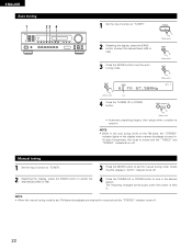
... DOWN button to tune in monaural and the "STEREO" indicator turns off . ENGLISH Auto tuning 1 B 23 4 1 Set the input function to "TUNER". 2 Watching the display, press the BAND button to select the desired band (AM or FM). 3 Press the MODE button to set the manual tuning mode. NOTE: • When in the auto tuning mode on the FM band, the "STEREO" indicator lights on the display when a stereo broadcast is muted and the "TUNED" and "STEREO" indicators turn off...
... DOWN button to tune in monaural and the "STEREO" indicator turns off . ENGLISH Auto tuning 1 B 23 4 1 Set the input function to "TUNER". 2 Watching the display, press the BAND button to select the desired band (AM or FM). 3 Press the MODE button to set the manual tuning mode. NOTE: • When in the auto tuning mode on the FM band, the "STEREO" indicator lights on the display when a stereo broadcast is muted and the "TUNED" and "STEREO" indicators turn off...
Owners Manual
Page 25
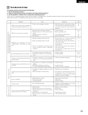
...; Power cord not plugged in securely. • Speaker cords not securely connected. • Improper position of the audio function button. • Volume control set is cooled down . Once the set to minimum. • MUTING is not operating properly, check the items listed in reverse. DISPLAY lit but sound not produced. Howling noise produced when volume is playing. Volume is distorted. This unit does not operate properly when remote control unit is used . •...
...; Power cord not plugged in securely. • Speaker cords not securely connected. • Improper position of the audio function button. • Volume control set is cooled down . Once the set to minimum. • MUTING is not operating properly, check the items listed in reverse. DISPLAY lit but sound not produced. Howling noise produced when volume is playing. Volume is distorted. This unit does not operate properly when remote control unit is used . •...


