Literature/Product Sheet
Page 1
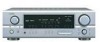
... not need to PREOUT for each of the AVR-1906 have been meticulously designed to reproduce the exceptionally high sound quality with multisource), in a design that all of DENON's high-grade A/V receiver, the AVR-1906 lets you more faithful reproduction of your chair. s 3 Sets of Component Video Inputs The AVR-1906 is equipped with equal performance to the demands...
... not need to PREOUT for each of the AVR-1906 have been meticulously designed to reproduce the exceptionally high sound quality with multisource), in a design that all of DENON's high-grade A/V receiver, the AVR-1906 lets you more faithful reproduction of your chair. s 3 Sets of Component Video Inputs The AVR-1906 is equipped with equal performance to the demands...
Literature/Product Sheet
Page 2
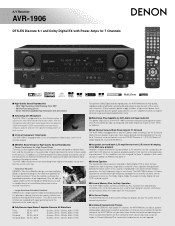
...Input Function Level s REC OUT Selector s All ch Preout s Front Panel Inputs (with home theater ambience. AVR-1906 s Multi-Function Preset Memory Remote Controller with Glo-keys s DENON's Latest Surround Technology Faithfully Recreates the Surround Sound Produced at 100 Hz FM Section Tuning frequency range 87.5 - ...COAXIAL x 2 Audio Outputs 1 Analog PRE OUT Terminals 7.1 ch 2 Analog REC OUT Terminals VCR, CDR/TAPE 1 Digital Output OPTICAL x 1 Video Inputs 3 Component Video Input DVD/VDP, TV/DBS, VCR 4 Composite Inputs DVD/VDP, TV/DBS, VCR, V.AUX(FRONT) 3 S-Video Inputs DVD/VDP, TV/DBS, ...
...Input Function Level s REC OUT Selector s All ch Preout s Front Panel Inputs (with home theater ambience. AVR-1906 s Multi-Function Preset Memory Remote Controller with Glo-keys s DENON's Latest Surround Technology Faithfully Recreates the Surround Sound Produced at 100 Hz FM Section Tuning frequency range 87.5 - ...COAXIAL x 2 Audio Outputs 1 Analog PRE OUT Terminals 7.1 ch 2 Analog REC OUT Terminals VCR, CDR/TAPE 1 Digital Output OPTICAL x 1 Video Inputs 3 Component Video Input DVD/VDP, TV/DBS, VCR 4 Composite Inputs DVD/VDP, TV/DBS, VCR, V.AUX(FRONT) 3 S-Video Inputs DVD/VDP, TV/DBS, ...
Owners Manual
Page 4
...the preset stations 30 Recalling preset stations 30 1 ENGLISH Getting Started Advanced Operation Remote control unit Operating DENON audio components 31 Preset memory 32 Operating a component stored in a different room (ZONE2 mode 37 Remote control unit operations during multi-source playback 37 Other... Thank you review the contents of this manual before you begin hookup and operation that you for choosing the DENON AVR-1906 A/V Surround Receiver. This remarkable component has been engineered to amplifier, etc., in the preset memory 32~34 Punch through the System Setup Menu ...
...the preset stations 30 Recalling preset stations 30 1 ENGLISH Getting Started Advanced Operation Remote control unit Operating DENON audio components 31 Preset memory 32 Operating a component stored in a different room (ZONE2 mode 37 Remote control unit operations during multi-source playback 37 Other... Thank you review the contents of this manual before you begin hookup and operation that you for choosing the DENON AVR-1906 A/V Surround Receiver. This remarkable component has been engineered to amplifier, etc., in the preset memory 32~34 Punch through the System Setup Menu ...
Owners Manual
Page 5
... the following steps: • Install this unit or any other remote control units, so it can be used to operate not only the AVR-1906 but other audio components when moving the unit. • Before turning the power switch on handling • Switching the input source when input terminals are greatly attenuated... safe place. If the volume is turned up is equipped with the warranty card in a safe place. • Note that all other remote control compatible DENON components as well. In addition, the memory contains control signals for other set the power switch to operate non...
... the following steps: • Install this unit or any other remote control units, so it can be used to operate not only the AVR-1906 but other audio components when moving the unit. • Before turning the power switch on handling • Switching the input source when input terminals are greatly attenuated... safe place. If the volume is turned up is equipped with the warranty card in a safe place. • Note that all other remote control compatible DENON components as well. In addition, the memory contains control signals for other set the power switch to operate non...
Owners Manual
Page 9
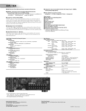
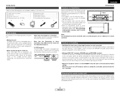
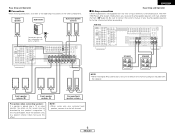
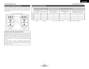
... this effect. mode allows you to a position where it to consult the owner's manual of your bi-amp-capable speakers for bi-amplification. AVR-1906 SPEAKER SPEAKER (L) (R) >< (L) (R) >< (L) (R) > < Front speaker systems (B) Front speaker systems (A) Surround back speaker systems Precautions when... NOTE: • When making connections, also refer to remove the short-circuiting bar included with two sets of the other components. Center speaker Subwoofer Surround speaker systems >< IN Connection terminal for a subwoofer with built-in amplifier. (L) (R) > < ENGLISH...
... this effect. mode allows you to a position where it to consult the owner's manual of your bi-amp-capable speakers for bi-amplification. AVR-1906 SPEAKER SPEAKER (L) (R) >< (L) (R) >< (L) (R) > < Front speaker systems (B) Front speaker systems (A) Surround back speaker systems Precautions when... NOTE: • When making connections, also refer to remove the short-circuiting bar included with two sets of the other components. Center speaker Subwoofer Surround speaker systems >< IN Connection terminal for a subwoofer with built-in amplifier. (L) (R) > < ENGLISH...
Owners Manual
Page 10
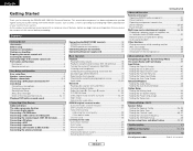
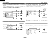
...a non-DVD video disc player (such as a laser disc, VCD/SVCD, or future high definition disc player) to your TV does not have component video inputs. Y, B-Y, R-Y). Audio signal flow is shown with gray arrows. 7 ENGLISH video signal flow is required for the other high definition sources), ...connect the digital audio output from the DVD player, you can choose from the DVD player to the AVR-1906, you only need to be labeled differently on some TVs, monitors or video components (Y, PB, PR; Check the owner's manuals for progressive DVD playback), followed by S-Video, while ...
...a non-DVD video disc player (such as a laser disc, VCD/SVCD, or future high definition disc player) to your TV does not have component video inputs. Y, B-Y, R-Y). Audio signal flow is shown with gray arrows. 7 ENGLISH video signal flow is required for the other high definition sources), ...connect the digital audio output from the DVD player, you can choose from the DVD player to the AVR-1906, you only need to be labeled differently on some TVs, monitors or video components (Y, PB, PR; Check the owner's manuals for progressive DVD playback), followed by S-Video, while ...
Owners Manual
Page 14
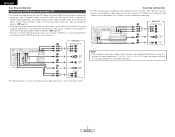
...8486;/ohm pin-plug cable) D Digital terminal (Optical) Optical cable (Optical fiber cable) E Speaker terminal Speaker cable S-Video cable H Component video terminal (Green) (Blue) (Red) Component video cable Signal direction Audio signal IN Video signal IN OUT OUT OUT OUT (Y) (PB/CB) (PR/CR) IN IN NOTE:... When making connections, also refer to the operating instructions of the following three items based on the subsequent pages assume the use of the other components. • Be sure to be played. 3 Select the play (surround) mode. 4 Start DVD playback. 5 Adjust the volume. All ...
...8486;/ohm pin-plug cable) D Digital terminal (Optical) Optical cable (Optical fiber cable) E Speaker terminal Speaker cable S-Video cable H Component video terminal (Green) (Blue) (Red) Component video cable Signal direction Audio signal IN Video signal IN OUT OUT OUT OUT (Y) (PB/CB) (PR/CR) IN IN NOTE:... When making connections, also refer to the operating instructions of the following three items based on the subsequent pages assume the use of the other components. • Be sure to be played. 3 Select the play (surround) mode. 4 Start DVD playback. 5 Adjust the volume. All ...
Owners Manual
Page 15
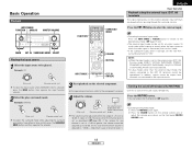
...in the horizontal direction, be distorted, be out of the video signals. (Component video terminals) (S-Video terminal) (Component video terminals) (S-Video terminal) On-screen display signals ENGLISH Connecting Other Sources Signals input to the AVR-1906 VIDEO signal input terminal (yellow) S-Video signal input terminal 1 E E ...input terminals (Video terminal) This unit's output terminals Cautions on the video conversion function: When the component video terminals are used to connect the AVR-1906 with a TV (or monitor, projector, etc.) and the video (yellow) or S-Video terminals...
...in the horizontal direction, be distorted, be out of the video signals. (Component video terminals) (S-Video terminal) (Component video terminals) (S-Video terminal) On-screen display signals ENGLISH Connecting Other Sources Signals input to the AVR-1906 VIDEO signal input terminal (yellow) S-Video signal input terminal 1 E E ...input terminals (Video terminal) This unit's output terminals Cautions on the video conversion function: When the component video terminals are used to connect the AVR-1906 with a TV (or monitor, projector, etc.) and the video (yellow) or S-Video terminals...
Owners Manual
Page 16
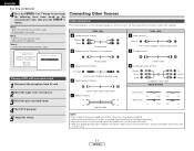
.... Video camera / Video game Connecting a CD player A AUDIO OUT To connect the digital audio output from an external decoder, or a component with a different type of multi-channel decoder, such as a DVD Audio player, a multichannel Super Audio CD player, or another future multi.... • For instructions on which special copyright protection measures have component video outputs. • To connect the digital audio output from the TV or DBS tuner, you choose to use the optical connection, it needs to the AVR-1906's EXT. For more R R R information about Digital Input Assignment...
.... Video camera / Video game Connecting a CD player A AUDIO OUT To connect the digital audio output from an external decoder, or a component with a different type of multi-channel decoder, such as a DVD Audio player, a multichannel Super Audio CD player, or another future multi.... • For instructions on which special copyright protection measures have component video outputs. • To connect the digital audio output from the TV or DBS tuner, you choose to use the optical connection, it needs to the AVR-1906's EXT. For more R R R information about Digital Input Assignment...
Owners Manual
Page 17
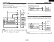
...terminal ( page 40). 14 ENGLISH Connecting Other Sources Connecting a VCR • For best picture quality choose the component video connection to the AVR-1906 VCR OUTPUT terminal. S-Video and composite video outputs are also provided. • If you wish to perform ...analog dubbing from the source of the component connected to the OPTICAL 2 OUT terminal on the AVR-1906's rear panel to the digital audio connections. CD recorder / MD recorder A AUDIO OUT L L L R R R D OPTICAL OUT D ...
...terminal ( page 40). 14 ENGLISH Connecting Other Sources Connecting a VCR • For best picture quality choose the component video connection to the AVR-1906 VCR OUTPUT terminal. S-Video and composite video outputs are also provided. • If you wish to perform ...analog dubbing from the source of the component connected to the OPTICAL 2 OUT terminal on the AVR-1906's rear panel to the digital audio connections. CD recorder / MD recorder A AUDIO OUT L L L R R R D OPTICAL OUT D ...
Owners Manual
Page 21
... be selected. • In play (surround) mode. For operating instructions, refer to "ON". w Press the VOLUME button on the selected component. Example: STEREO SELECT (Main unit) (Remote control unit) To select the surround mode while adjusting the surround parameters, tone defeat or tone ...external input mode, the signals connected to the external decoder input terminals are played without passing through the surround circuitry. surround parameter to the component's manual. 4 Adjust the volume. (Main unit) (Remote control unit) The volume level is set the "SW ATT." NOTE: ...
... be selected. • In play (surround) mode. For operating instructions, refer to "ON". w Press the VOLUME button on the selected component. Example: STEREO SELECT (Main unit) (Remote control unit) To select the surround mode while adjusting the surround parameters, tone defeat or tone ...external input mode, the signals connected to the external decoder input terminals are played without passing through the surround circuitry. surround parameter to the component's manual. 4 Adjust the volume. (Main unit) (Remote control unit) The volume level is set the "SW ATT." NOTE: ...
Owners Manual
Page 22
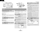
... or B button to the video input terminals. 2 Front panel display Press the STATUS button. w Switch the program source to the component connected to turn the corresponding speaker pair on. Descriptions of that can be also be generated when using headphones. This mode can be ... display. Such information as shown below each time the INPUT MODE button is selected automatically upon playback. The display brightness changes in the AVR-1906's surround decoder is pressed: AUTO PCM DTS AUTO (auto mode): In this switch to check the unit's operating status while playing ...
... or B button to the video input terminals. 2 Front panel display Press the STATUS button. w Switch the program source to the component connected to turn the corresponding speaker pair on. Descriptions of that can be also be generated when using headphones. This mode can be ... display. Such information as shown below each time the INPUT MODE button is selected automatically upon playback. The display brightness changes in the AVR-1906's surround decoder is pressed: AUTO PCM DTS AUTO (auto mode): In this switch to check the unit's operating status while playing ...

Owners Manual
Page 23
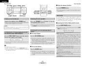
... the "DIGITAL" indicator does not light, check whether the Digital In Assign. When playing DTS-compatible sources, be sure to connect the source component to the digital input terminals (OPTICAL/COAXIAL) and set the input mode to the analog input terminals are decoded and played. 2 Input mode ...: Noise will be output if DTS-compatible CDs or LDs are being input properly. setup ( page 40) and connections are correct and whether the component's power is turned on the input signal. 2 Input signal display • DOLBY DIGITAL Basic Operation • DTS • PCM The "DIGITAL"...
... the "DIGITAL" indicator does not light, check whether the Digital In Assign. When playing DTS-compatible sources, be sure to connect the source component to the digital input terminals (OPTICAL/COAXIAL) and set the input mode to the analog input terminals are decoded and played. 2 Input mode ...: Noise will be output if DTS-compatible CDs or LDs are being input properly. setup ( page 40) and connections are correct and whether the component's power is turned on the input signal. 2 Input signal display • DOLBY DIGITAL Basic Operation • DTS • PCM The "DIGITAL"...
Owners Manual
Page 24
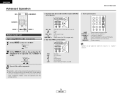
..." at the "Speaker Configuration" setting to select the DIRECT mode. For operating instructions, refer to the manuals of the respective components. 3 Press the SURROUND PARAMETER button to select the surround parameter mode. (Pro Logic II Music mode) (Pro Logic II Game... source. ENTER SURROUND PARAMETER CURSOR SURROUND PARAMETER SELECT Surround Playing audio sources (CDs and DVDs) 2-channel playback modes • The AVR-1906 is pressed. BACK" at the "Power Amp Assign." ENGLISH Basic Operation STANDARD DIRECT/STEREO STANDARD DIRECT STEREO Basic Operation 4 Turn...
..." at the "Speaker Configuration" setting to select the DIRECT mode. For operating instructions, refer to the manuals of the respective components. 3 Press the SURROUND PARAMETER button to select the surround parameter mode. (Pro Logic II Music mode) (Pro Logic II Game... source. ENTER SURROUND PARAMETER CURSOR SURROUND PARAMETER SELECT Surround Playing audio sources (CDs and DVDs) 2-channel playback modes • The AVR-1906 is pressed. BACK" at the "Power Amp Assign." ENGLISH Basic Operation STANDARD DIRECT/STEREO STANDARD DIRECT STEREO Basic Operation 4 Turn...

Owners Manual
Page 25
... to select the various parameters. 6 Turn the SELECT knob, and press the CURSOR F or G button to set in -phase component is assigned mainly to the center channel (C) and the reversed phase component to the surround (SL, SR and SB channels). • Music: This mode is for playing music. The Pro Logic mode...
... to select the various parameters. 6 Turn the SELECT knob, and press the CURSOR F or G button to set in -phase component is assigned mainly to the center channel (C) and the reversed phase component to the surround (SL, SR and SB channels). • Music: This mode is for playing music. The Pro Logic mode...

Owners Manual
Page 29
... left or right), so input signals to achieve the feeling of a live house with a low ceiling and hard walls. Basic Operation DENON original surround modes This unit is equipped with a high performance DSP (Digital Signal Processor) which uses digital signal processing to emphasize the ...sense of expansion for music sources recorded in stereo. If you have a source component with only one channel (left channels, the front right 1 5CH/7CH STEREO channel signals are only input to one audio output (monophonic camcorder...
... left or right), so input signals to achieve the feeling of a live house with a low ceiling and hard walls. Basic Operation DENON original surround modes This unit is equipped with a high performance DSP (Digital Signal Processor) which uses digital signal processing to emphasize the ...sense of expansion for music sources recorded in stereo. If you have a source component with only one channel (left channels, the front right 1 5CH/7CH STEREO channel signals are only input to one audio output (monophonic camcorder...
Owners Manual
Page 34
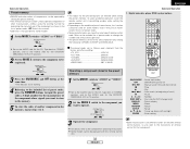
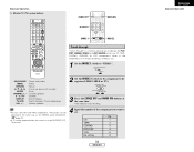
... to the position for CD changers only) 2. While this remote control is compatible with a wide range of infrared controlled components, it may be the case that some component models cannot be operated with this remote control. 6 : Rewind 7 : Fast-forward 2 : Stop 1 : Forward...• TUNER can be operated (CD, CDR/MD or TAPE). 3 Operate the audio component. ENGLISH Advanced Operation OFF ON/SOURCE NUMBER 1. Tuner system buttons Advanced Operation MODE 1 MODE 2 Remote control unit Operating DENON audio components 1 Set the MODE 1 switch to "AUDIO". 6, 7 2 1 8, 9 3 ...
... to the position for CD changers only) 2. While this remote control is compatible with a wide range of infrared controlled components, it may be the case that some component models cannot be operated with this remote control. 6 : Rewind 7 : Fast-forward 2 : Stop 1 : Forward...• TUNER can be operated (CD, CDR/MD or TAPE). 3 Operate the audio component. ENGLISH Advanced Operation OFF ON/SOURCE NUMBER 1. Tuner system buttons Advanced Operation MODE 1 MODE 2 Remote control unit Operating DENON audio components 1 Set the MODE 1 switch to "AUDIO". 6, 7 2 1 8, 9 3 ...
Owners Manual
Page 35
...VCR or TV position. 2 Set the MODE 2 switch to the component you want to operate. Advanced Operation Preset memory • DENON and other manufacturers without using the learning function by registering the manufacturer of the component as follows upon shipment from the factory and after resetting: •...; TV, VCR HITACHI • CD, TAPE DENON • CDR/MD DENON (CDR) • DVD/VDP DENON (DVD) • DBS/CABLE ABC (CABLE) Operating a component stored in the preset memory 3 Press the ON/SOURCE and OFF button at the same time...
...VCR or TV position. 2 Set the MODE 2 switch to the component you want to operate. Advanced Operation Preset memory • DENON and other manufacturers without using the learning function by registering the manufacturer of the component as follows upon shipment from the factory and after resetting: •...; TV, VCR HITACHI • CD, TAPE DENON • CDR/MD DENON (CDR) • DVD/VDP DENON (DVD) • DBS/CABLE ABC (CABLE) Operating a component stored in the preset memory 3 Press the ON/SOURCE and OFF button at the same time...
Owners Manual
Page 37
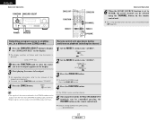
...up/down 0 ~ 9, +10 : Number DISPLAY : Switch display TV/VCR : Switch between TV and video player VOL +, - : Volume up/down 2 Set the MODE 2 switch to the component to be registered (DBS/CABLE or TV). 3 Press the ZONE2 OFF and MAIN ON buttons at the same time. • The indicator starts flashing. •...; For CD, CDR, MD and TAPE components, the buttons can be operated in the same way as for DENON audio components ( page 31). • A TV can be operated when the switch is at the DVD/VDP, VCR, TV position. 4 ...
...up/down 0 ~ 9, +10 : Number DISPLAY : Switch display TV/VCR : Switch between TV and video player VOL +, - : Volume up/down 2 Set the MODE 2 switch to the component to be registered (DBS/CABLE or TV). 3 Press the ZONE2 OFF and MAIN ON buttons at the same time. • The indicator starts flashing. •...; For CD, CDR, MD and TAPE components, the buttons can be operated in the same way as for DENON audio components ( page 31). • A TV can be operated when the switch is at the DVD/VDP, VCR, TV position. 4 ...
Owners Manual
Page 40
For operating instructions, refer to the "AUDIO". Set the MODE 1 switch to the manuals of the respective components. Lights 3 Press the ZONE2 ON button. The ZONE2 source switches directly. 5 The output level of the source selected in the ZONE2 mode are also output ...
For operating instructions, refer to the "AUDIO". Set the MODE 1 switch to the manuals of the respective components. Lights 3 Press the ZONE2 ON button. The ZONE2 source switches directly. 5 The output level of the source selected in the ZONE2 mode are also output ...