
Service Manual
Page 1
Dell Latitude D400 Service Manual Dell™ Latitude™ D400 Service Manual Before You Begin Preparing to Work Inside the Computer Recommended Tools Computer Orientation Screw Identification Using the Dell Diagnostics When to Use the Dell Diagnostics Features of the Dell Diagnostics Starting the Dell Diagnostics System Components Keyboard Removing the Keyboard Installing the Keyboard Memory... Doors Bluetooth™ Display Removing the Display Assembly Replacing the Display Latch Palm Rest Cooling Fan file:///F|/Service%20Manuals/Dell/Latitude/d400/index.htm (1 of 3) [2/28/2004 8:05:56 AM]
Dell Latitude D400 Service Manual Dell™ Latitude™ D400 Service Manual Before You Begin Preparing to Work Inside the Computer Recommended Tools Computer Orientation Screw Identification Using the Dell Diagnostics When to Use the Dell Diagnostics Features of the Dell Diagnostics Starting the Dell Diagnostics System Components Keyboard Removing the Keyboard Installing the Keyboard Memory... Doors Bluetooth™ Display Removing the Display Assembly Replacing the Display Latch Palm Rest Cooling Fan file:///F|/Service%20Manuals/Dell/Latitude/d400/index.htm (1 of 3) [2/28/2004 8:05:56 AM]

Service Manual
Page 2
... better use of Microsoft Corporation; and is a trademark owned by Dell Inc. disclaims any proprietary interest in this document to refer to either potential damage to avoid the problem. Dell Latitude D400 Service Manual Touch Pad System Board Removing the System Board Replacing the.... Trademarks used in trademarks and trade names other than its own. file:///F|/Service%20Manuals/Dell/Latitude/d400/index.htm (2 of Dell Inc.; Other trademarks and trade names may be used by Bluetooth SIG, Inc. Dell Inc. under license. Microsoft and Windows are trademarks of 3) [2/28/2004 8:05:56...
... better use of Microsoft Corporation; and is a trademark owned by Dell Inc. disclaims any proprietary interest in this document to refer to either potential damage to avoid the problem. Dell Latitude D400 Service Manual Touch Pad System Board Removing the System Board Replacing the.... Trademarks used in trademarks and trade names other than its own. file:///F|/Service%20Manuals/Dell/Latitude/d400/index.htm (2 of Dell Inc.; Other trademarks and trade names may be used by Bluetooth SIG, Inc. Dell Inc. under license. Microsoft and Windows are trademarks of 3) [2/28/2004 8:05:56...

Service Manual
Page 4
...Work Inside the Computer CAUTION: Only a certified service technician should perform repairs on a card. file:///F|/Service%20Manuals/Dell/Latitude/d400/begin working inside your computer, discharge static electricity from your body before you touch any work surface is not...card by its edges, not by touching an unpainted metal surface. Before You Begin: Dell Latitude D400 Service Manual Back to Contents Page Before You Begin Dell™ Latitude™ D400 Service Manual Preparing to Work Inside the Computer Recommended Tools Computer Orientation Screw Identification Preparing to...
...Work Inside the Computer CAUTION: Only a certified service technician should perform repairs on a card. file:///F|/Service%20Manuals/Dell/Latitude/d400/begin working inside your computer, discharge static electricity from your body before you touch any work surface is not...card by its edges, not by touching an unpainted metal surface. Before You Begin: Dell Latitude D400 Service Manual Back to Contents Page Before You Begin Dell™ Latitude™ D400 Service Manual Preparing to Work Inside the Computer Recommended Tools Computer Orientation Screw Identification Preparing to...
Service Manual
Page 5
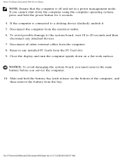
... computer upside down the computer using the computer operating system, press and hold the battery-bay latch release on a flat work surface. Before You Begin: Dell Latitude D400 Service Manual NOTE: Ensure that the computer is connected to 20 seconds and then disconnect any installed PC Cards from the electrical outlet. 6. file:///F|/Service...
... computer upside down the computer using the computer operating system, press and hold the battery-bay latch release on a flat work surface. Before You Begin: Dell Latitude D400 Service Manual NOTE: Ensure that the computer is connected to 20 seconds and then disconnect any installed PC Cards from the electrical outlet. 6. file:///F|/Service...

Service Manual
Page 6
Before You Begin: Dell Latitude D400 Service Manual Recommended Tools The procedures in this manual require the following tools: q Phillips screwdriver q Flat-blade screwdriver q Small plastic scribe q Flash BIOS update program floppy disk or CD Computer Orientation file:///F|/Service%20Manuals/Dell/Latitude/d400/begin.htm (3 of 7) [2/28/2004 8:06:07 AM]
Before You Begin: Dell Latitude D400 Service Manual Recommended Tools The procedures in this manual require the following tools: q Phillips screwdriver q Flat-blade screwdriver q Small plastic scribe q Flash BIOS update program floppy disk or CD Computer Orientation file:///F|/Service%20Manuals/Dell/Latitude/d400/begin.htm (3 of 7) [2/28/2004 8:06:07 AM]

Service Manual
Page 7
The screw identification chart provides the number of 7) [2/28/2004 8:06:07 AM] file:///F|/Service%20Manuals/Dell/Latitude/d400/begin.htm (4 of screws and their sizes. Before You Begin: Dell Latitude D400 Service Manual 1 back 2 right 3 front 4 left Screw Identification When you are removing and replacing components, photocopy "Screw Identification" as a tool to lay out and keep track of the screws.
The screw identification chart provides the number of 7) [2/28/2004 8:06:07 AM] file:///F|/Service%20Manuals/Dell/Latitude/d400/begin.htm (4 of screws and their sizes. Before You Begin: Dell Latitude D400 Service Manual 1 back 2 right 3 front 4 left Screw Identification When you are removing and replacing components, photocopy "Screw Identification" as a tool to lay out and keep track of the screws.

Service Manual
Page 9
Before You Begin: Dell Latitude D400 Service Manual palm rest fan system board (thirteen each) (three each) (six each) 4911U (two each) 1428U 1428U (one each, if a BIOS card is present) 5H953 speakers (two each) 1428U 4911U Back to Contents Page file:///F|/Service%20Manuals/Dell/Latitude/d400/begin.htm (6 of 7) [2/28/2004 8:06:07 AM]
Before You Begin: Dell Latitude D400 Service Manual palm rest fan system board (thirteen each) (three each) (six each) 4911U (two each) 1428U 1428U (one each, if a BIOS card is present) 5H953 speakers (two each) 1428U 4911U Back to Contents Page file:///F|/Service%20Manuals/Dell/Latitude/d400/begin.htm (6 of 7) [2/28/2004 8:06:07 AM]

Service Manual
Page 11
... with important information you to resolve the problem yourself quickly without destroying any data. file:///F|/Service%20Manuals/Dell/Latitude/d400/diag.htm (1 of the Dell Diagnostics The Dell Diagnostics helps you are unsure about how to test only your Dell computer. If you to check your computer hardware without any additional equipment and without having to...
... with important information you to resolve the problem yourself quickly without destroying any data. file:///F|/Service%20Manuals/Dell/Latitude/d400/diag.htm (1 of the Dell Diagnostics The Dell Diagnostics helps you are unsure about how to test only your Dell computer. If you to check your computer hardware without any additional equipment and without having to...

Service Manual
Page 12
.... See the documentation that appear if any problems are detected Starting the Dell Diagnostics The Dell Diagnostics is connected to select tests based on your computer cannot display a screen image, contact Dell. Connect the computer to terminate testing q Extensive online Help that describes...groups or subtests were completed successfully q Error messages that came with your docking device for contact information. 1. file:///F|/Service%20Manuals/Dell/Latitude/d400/diag.htm (2 of times a test group or subtest is repeated q The ability to display test results q Options to temporarily...
.... See the documentation that appear if any problems are detected Starting the Dell Diagnostics The Dell Diagnostics is connected to select tests based on your computer cannot display a screen image, contact Dell. Connect the computer to terminate testing q Extensive online Help that describes...groups or subtests were completed successfully q Error messages that came with your docking device for contact information. 1. file:///F|/Service%20Manuals/Dell/Latitude/d400/diag.htm (2 of times a test group or subtest is repeated q The ability to display test results q Options to temporarily...

Service Manual
Page 13
...completes successfully, you receive the message Booting Dell Diagnostic Utility Partition. The computer automatically runs the Pre-boot System Assessment. 4. The computer begins to the operating system, press ; file:///F|/Service%20Manuals/Dell/Latitude/d400/diag.htm (3 of embedded diagnostics that ...appear. Then shut down your system board, keyboard, hard drive, and display. To stop the assessment and reboot to run the Dell Diagnostics from the Diagnostics utility partition...
...completes successfully, you receive the message Booting Dell Diagnostic Utility Partition. The computer automatically runs the Pre-boot System Assessment. 4. The computer begins to the operating system, press ; file:///F|/Service%20Manuals/Dell/Latitude/d400/diag.htm (3 of embedded diagnostics that ...appear. Then shut down your system board, keyboard, hard drive, and display. To stop the assessment and reboot to run the Dell Diagnostics from the Diagnostics utility partition...

Service Manual
Page 14
...conditions encountered, error codes, and problem description. Describes the test and may indicate requirements for contact information. 9. file:///F|/Service%20Manuals/Dell/Latitude/d400/diag.htm (4 of the test and any error conditions encountered. Write down the error code and problem description and follow the ...typically takes 1 hour or more information. The option lists the most common symptoms. 8. Custom Test Tests a specific device. Using the Dell Diagnostics: NOTE: The Service Tag for your part. Run Express Test first to select tests based on a symptom of tracing the problem ...
...conditions encountered, error codes, and problem description. Describes the test and may indicate requirements for contact information. 9. file:///F|/Service%20Manuals/Dell/Latitude/d400/diag.htm (4 of the test and any error conditions encountered. Write down the error code and problem description and follow the ...typically takes 1 hour or more information. The option lists the most common symptoms. 8. Custom Test Tests a specific device. Using the Dell Diagnostics: NOTE: The Service Tag for your part. Run Express Test first to select tests based on a symptom of tracing the problem ...

Service Manual
Page 15
Using the Dell Diagnostics: Configuration Displays your hardware configuration for all devices from the system setup program, memory, and various internal tests and displays the information in the ... (see the User's Guide for information on your computer or all devices attached to Contents Page file:///F|/Service%20Manuals/Dell/Latitude/d400/diag.htm (5 of 5) [2/28/2004 8:06:08 AM] To exit the Dell Diagnostics and reboot the computer, close the screen to return to customize the test by changing the test settings. 10...
Using the Dell Diagnostics: Configuration Displays your hardware configuration for all devices from the system setup program, memory, and various internal tests and displays the information in the ... (see the User's Guide for information on your computer or all devices attached to Contents Page file:///F|/Service%20Manuals/Dell/Latitude/d400/diag.htm (5 of 5) [2/28/2004 8:06:08 AM] To exit the Dell Diagnostics and reboot the computer, close the screen to return to customize the test by changing the test settings. 10...

Service Manual
Page 16
NOTICE: Unless otherwise noted, each procedure in reverse order. file:///F|/Service%20Manuals/Dell/Latitude/d400/system.htm (1 of 2) [2/28/2004 8:06:09 AM] System Components: Back to servicing that is not authorized by Dell is not covered by performing the removal procedure in this document assumes that a part can be replaced by your computer. Damage due to Contents Page System Components NOTICE: Only a certified service technician should perform repairs on your warranty.
NOTICE: Unless otherwise noted, each procedure in reverse order. file:///F|/Service%20Manuals/Dell/Latitude/d400/system.htm (1 of 2) [2/28/2004 8:06:09 AM] System Components: Back to servicing that is not authorized by Dell is not covered by performing the removal procedure in this document assumes that a part can be replaced by your computer. Damage due to Contents Page System Components NOTICE: Only a certified service technician should perform repairs on your warranty.

Service Manual
Page 18
Open the display approximately 180 degrees. 3. file:///F|/Service%20Manuals/Dell/Latitude/d400/keyboard.htm (1 of the center control cover, and pry the cover loose from the bottom case. Keyboard: Back to Contents Page Keyboard Removing the Keyboard ...
Open the display approximately 180 degrees. 3. file:///F|/Service%20Manuals/Dell/Latitude/d400/keyboard.htm (1 of the center control cover, and pry the cover loose from the bottom case. Keyboard: Back to Contents Page Keyboard Removing the Keyboard ...

Service Manual
Page 19
Use the pull-tab to pull the keyboard up and out (toward the display) of 5) [2/28/2004 8:06:10 AM] file:///F|/Service%20Manuals/Dell/Latitude/d400/keyboard.htm (2 of the bottom case. Remove the two M2 x 5-mm screws from the top of the keyboard. 5. Keyboard: 1 center control cover 5U447 4.
Use the pull-tab to pull the keyboard up and out (toward the display) of 5) [2/28/2004 8:06:10 AM] file:///F|/Service%20Manuals/Dell/Latitude/d400/keyboard.htm (2 of the bottom case. Remove the two M2 x 5-mm screws from the top of the keyboard. 5. Keyboard: 1 center control cover 5U447 4.

Service Manual
Page 20
file:///F|/Service%20Manuals/Dell/Latitude/d400/keyboard.htm (3 of 5) [2/28/2004 8:06:10 AM] Keyboard: 1 keyboard P1290 2 keyboard pull-tab 3 M2 x 5-mm screws (2) 1428U 4 securing tabs (5) 6. Pull straight up on the pull-tab that is attached to the keyboard connector to disconnect the connector from the interface connector on the palm rest. 7. Rest the keyboard face down on the system board.
file:///F|/Service%20Manuals/Dell/Latitude/d400/keyboard.htm (3 of 5) [2/28/2004 8:06:10 AM] Keyboard: 1 keyboard P1290 2 keyboard pull-tab 3 M2 x 5-mm screws (2) 1428U 4 securing tabs (5) 6. Pull straight up on the pull-tab that is attached to the keyboard connector to disconnect the connector from the interface connector on the palm rest. 7. Rest the keyboard face down on the system board.

Service Manual
Page 21
Replace the two screws at the top of 5) [2/28/2004 8:06:10 AM] Connect the keyboard connector to the right side so that it is flush with the palm rest. Insert the five securing tabs on the system board. 2. Keyboard: 1 pull-tab on the left side and working to the interface connector on the keyboard into their respective slots in the palm rest. 3. Replace the center control cover and snap it down starting on keyboard connector 2 keyboard connector Installing the Keyboard 1. file:///F|/Service%20Manuals/Dell/Latitude/d400/keyboard.htm (4 of the keyboard. 4.
Replace the two screws at the top of 5) [2/28/2004 8:06:10 AM] Connect the keyboard connector to the right side so that it is flush with the palm rest. Insert the five securing tabs on the system board. 2. Keyboard: 1 pull-tab on the left side and working to the interface connector on the keyboard into their respective slots in the palm rest. 3. Replace the center control cover and snap it down starting on keyboard connector 2 keyboard connector Installing the Keyboard 1. file:///F|/Service%20Manuals/Dell/Latitude/d400/keyboard.htm (4 of the keyboard. 4.

Service Manual
Page 23
Continue to remove the battery and prepare the computer for work. 2. file:///F|/Service%20Manuals/Dell/Latitude/d400/memory.htm (1 of 7) [2/28/2004 8:06:11 AM] Turn the computer over, loosen the captive screws on the computer. 1. NOTICE: To avoid electrostatic discharge, ground ...
Continue to remove the battery and prepare the computer for work. 2. file:///F|/Service%20Manuals/Dell/Latitude/d400/memory.htm (1 of 7) [2/28/2004 8:06:11 AM] Turn the computer over, loosen the captive screws on the computer. 1. NOTICE: To avoid electrostatic discharge, ground ...

Service Manual
Page 24
b. If you are replacing a memory module, remove the existing module: a. Remove the module from the connector. Use your fingertips to spread the memory-module securing clips. 2. file:///F|/Service%20Manuals/Dell/Latitude/d400/memory.htm (2 of the memory module connector until the module pops up. Memory: 1 captive screws (2) 2 memory module/modem cover P0777 NOTICE: To prevent damage to the memory module connector, do not use tools to carefully spread apart the securing clips on each end of 7) [2/28/2004 8:06:11 AM]
b. If you are replacing a memory module, remove the existing module: a. Remove the module from the connector. Use your fingertips to spread the memory-module securing clips. 2. file:///F|/Service%20Manuals/Dell/Latitude/d400/memory.htm (2 of the memory module connector until the module pops up. Memory: 1 captive screws (2) 2 memory module/modem cover P0777 NOTICE: To prevent damage to the memory module connector, do not use tools to carefully spread apart the securing clips on each end of 7) [2/28/2004 8:06:11 AM]

Service Manual
Page 25
... click, remove the module and reinstall it clicks into the slot at a 45-degree angle, and rotate the module down until it . file:///F|/Service%20Manuals/Dell/Latitude/d400/memory.htm (3 of 7) [2/28/2004 8:06:11 AM] Memory: 1 memory module See Mini RSL 2 securing clips (2) 3. NOTE: If the memory module is not installed properly...
... click, remove the module and reinstall it clicks into the slot at a 45-degree angle, and rotate the module down until it . file:///F|/Service%20Manuals/Dell/Latitude/d400/memory.htm (3 of 7) [2/28/2004 8:06:11 AM] Memory: 1 memory module See Mini RSL 2 securing clips (2) 3. NOTE: If the memory module is not installed properly...


